Point-type heat fire detector

A fire detector, point-type technology, applied in the direction of electrical fire alarms, etc., can solve the problems of low light transmission efficiency, assembly production efficiency and maintenance efficiency, reduced manufacturing production efficiency, and failure of fire alarm devices, etc. Light capture rate, improved production efficiency, simple assembly effect

Inactive Publication Date: 2013-01-30
北京福赛尔安全消防设备有限公司
View PDF8 Cites 4 Cited by
  • Summary
  • Abstract
  • Description
  • Claims
  • Application Information

AI Technical Summary

Problems solved by technology

In the existing point-type temperature-sensitive fire detectors, the light-guiding column used for luminous display is installed on the top or side of the entire point-type temperature-sensitive fire detector in the form of a straight column perpendicular to the circuit board or in the form of a 90-degree refraction angle. Insufficient aesthetics, poor display effect, low light transmission efficiency, assembly production efficiency and maintenance efficiency; and a large number of screws are used in the assembly structure of point-type temperature-sensitive fire detectors. For example, circuit board screw connections are generally used, and countersunk heads are used Screws or combined screws, etc., increase the cost and reduce the manufacturing efficiency; in addition, the existing point-type temperature-sensitive fire detectors do not have a waterproof structure, which will cause the circuit board to fail when it encounters water, thus causing the fire alarm device to fail serious consequences

Method used


Image

  • Point-type heat fire detector
  • Point-type heat fire detector
  • Point-type heat fire detector

Examples


Embodiment Construction

[0047] The present invention will be described below with reference to the accompanying drawings.

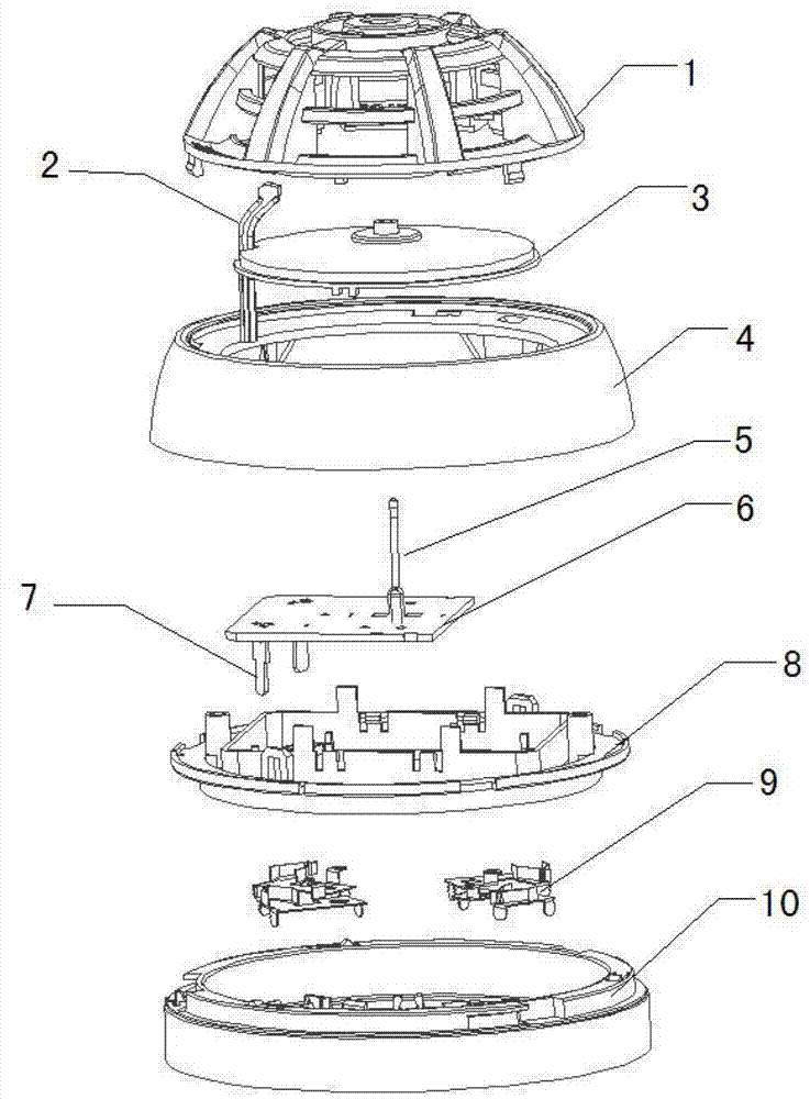
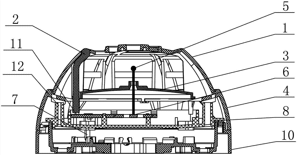
[0048] The present invention relates to a point-type temperature-sensing fire detector, the schematic diagram of the explosion structure and the schematic diagram of the assembled structure are respectively as follows figure 1 and figure 2 As shown, it includes a casing and a circuit board 6 inside the casing, a light guide column 2 and a plate-shaped middle buckle 8. The casing includes a base 10, an annular middle cover 4 and an upper cover 1 connected in sequence, the base 10, the annular middle cover 4 and the upper cover 1. The outer contour formed by the cover 1 is in the shape of a hemispherical table, the upper cover 1 is located at the top of the hemispherical table, the middle button 8 is snap-connected and arranged in the annular middle cover 4, the circuit board 6 is snap-fitted on the middle button 8, and the circuit board 6 is provided with a The thermistor 5 and...


PUM


Abstract

The invention relates to a point-type heat fire detector. The point-type heat fire detector comprises a shell and a circuit board in the shell, wherein a thermistor and a light emitting diode are arranged on the circuit board; a light guide column and a plate-like middle fastener are arranged in the shell; the shell comprises a base, an annular middle cover and an upper cover, which are sequentially connected; an outer contour which consists of the base, the annular middle cover and the upper cover is in a shape of a hemispherical table; the upper cover is positioned on the top of the hemispherical table; the middle fastener is clamped in the annular middle cover; the circuit board is clamped on the middle fastener; the surface of a light emitting part of the light emitting diode faces the upper cover; the light guide column has a columnar bending structure; one end of the light guide column faces and approaches the light emitting part of the light emitting diode, and the other end of the light guide column is bent to the top of the upper cover along the radian of the upper cover and corresponds to an annular through structure which is arranged on the upper cover; and one end of the light guide column, which is bent along the radian of the upper cover, is bent back at the end head, so the light conduction directions of the end heads of the two ends of the light guide column are the same. By adoption of the point-type heat fire detector, a light emitting display effect can be improved, an installation process is simplified, and reliability is improved.

Description

technical field [0001] The invention relates to the technical field of fire detection and alarm, in particular to a novel point-type temperature-sensing fire detector. Background technique [0002] With the intelligent development of modern buildings, the increase of combustible materials such as electrical equipment or decoration materials in buildings, there are potential safety hazards, fire alarm devices have increasingly become an indispensable safety facility in large buildings and public places. Destroy the fire at the initial stage. At present, the fire alarm device often used in the fire protection industry is a point-type temperature-sensing fire detector. In the existing point-type heat-sensing fire detector, the light-guiding column used for luminous display is installed on the top or side of the entire point-type temperature-sensing fire detector in the form of a straight column and a vertical circuit board or in the form of a 90-degree refraction angle. Insuf...

Claims


Application Information

Patent Timeline
Patent Type & Authority Applications(China)
IPC IPC(8): G08B17/06
Inventor 蒋永亮彭晓波王爱洁
Owner 北京福赛尔安全消防设备有限公司
Why Eureka
Try Eureka