

Multi-frequency broadband antenna based on broadband antenna and trapped wave structure
A broadband antenna and wave trap technology, applied in the field of multi-frequency antenna structure, can solve the problems of narrow frequency band, difficult adjustment of resonance point, complex antenna structure, etc.
- Summary
- Abstract
- Description
- Claims
- Application Information
AI Technical Summary
Problems solved by technology
Method used
Image

Examples
Embodiment Construction
[0021] The present invention will be further described in detail below in conjunction with the accompanying drawings and embodiments.
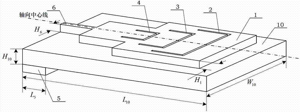
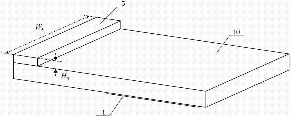
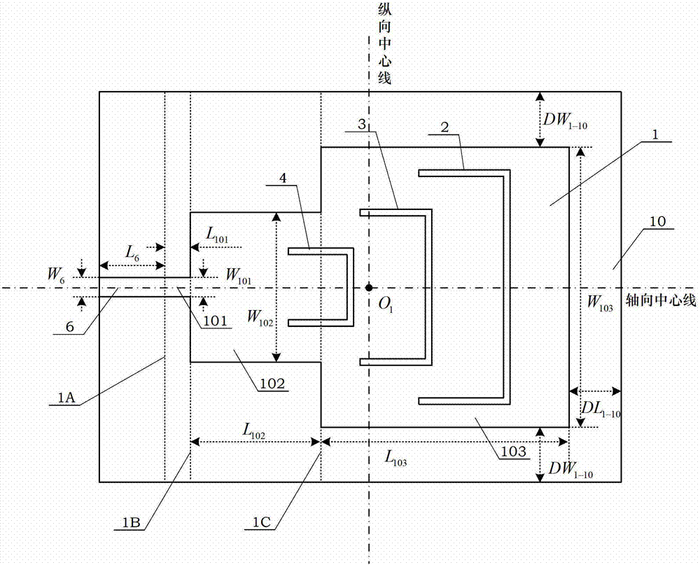
[0022] see figure 1 , Figure 1A Shown, a kind of multi-frequency broadband antenna based on broadband antenna and notch structure of the present invention, this antenna is made up of radiator 1, the first U-shaped slot 2, the second U-shaped slot 3, the third U-shaped slot 4, the floor 5. The feeder 6 and the dielectric board 10 are composed; the radiator 1 and the feeder 6 are deposited on one surface of the dielectric board 10 by a copper-clad process, and the floor 5 is deposited on the other board surface of the dielectric board 10 by a copper-clad process. Radiator 1 and feeder 6 are clad with copper; the copper thickness of radiator 1 (H 1 ) is 0.01mm, the copper thickness of the feeder 6 (H 6 ) is 0.01mm, the copper thickness of floor 5 (H 5 ) is 0.01 mm; the first U-shaped slit 2 , the second U-shaped slit 3 and the third U-shaped...
PUM
 Abstract
Description
Claims
Application Information