Magnetic resonance imaging device and method for modulating high frequency magnetic field pulses

A technology of magnetic resonance imaging and high-frequency magnetic field, which is applied in magnetic resonance measurement, measurement device, measurement of magnetic variables, etc., can solve problems such as image quality deterioration, and achieve the effect of good image quality

Inactive Publication Date: 2013-01-30
HITACHI MEDICAL CORP
View PDF3 Cites 5 Cited by
  • Summary
  • Abstract
  • Description
  • Claims
  • Application Information

AI Technical Summary

Problems solved by technology

When a half RF pulse is used, the timing at which the gradient magnetic field changes (the fall time of the gradient magnetic field) occurs during the high output time (near the peak output) of the RF pulse, so the estimation error of the actual gradient magnetic field response involves high frequency The modulation error of the magnetic field pulse significantly degrades the image quality

Method used


Image

  • Magnetic resonance imaging device and method for modulating high frequency magnetic field pulses
  • Magnetic resonance imaging device and method for modulating high frequency magnetic field pulses
  • Magnetic resonance imaging device and method for modulating high frequency magnetic field pulses

Examples


no. 1 approach

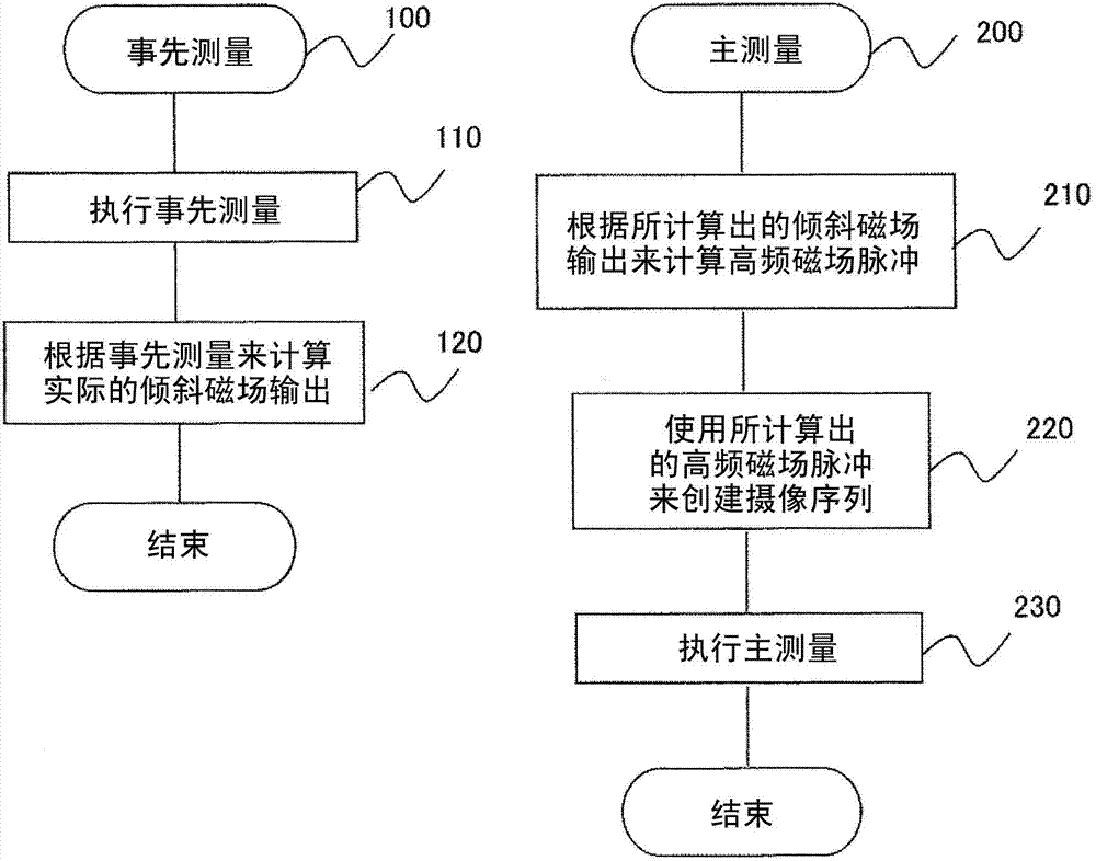
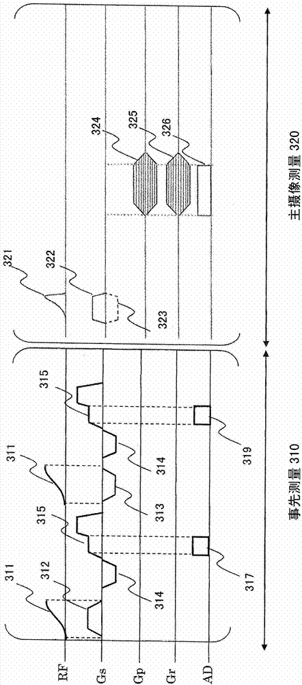
[0045] figure 2 Indicates the operation process of this embodiment, image 3 A pulse sequence diagram of the present embodiment is shown.

[0046] Such as figure 2 As shown, imaging in this embodiment is composed of pre-measurement 100 for measuring a gradient magnetic field pulse, and main measurement 200 using an RF pulse shape determined based on the result of the pre-measurement.

[0047] The previous measurement 100 is a measurement for calculating the output of the slice gradient magnetic field applied under the same conditions as the slice gradient magnetic field used in the main measurement 200, by image 3 The execution step 110 of the shown prior measurement pulse sequence 310 and the subsequent calculation step 120 of the gradient field output (response of the actual gradient field) constitute. The main measurement 200 is the measurement based on the UTE imaging sequence in this embodiment, and is composed of the following steps: the calculation step 210 using ...

no. 2 approach

[0098] Next, an embodiment in which the present invention is applied to an MRI apparatus that continuously performs imaging while changing slice selection conditions will be described. The continuous imaging targeted by this embodiment includes, for example, dynamic imaging in which imaging is performed while interactively changing slice sections and imaging conditions in accordance with subject movements such as joint bending motions, and switching from 3D imaging to 2D imaging. camera etc.

[0099] Figure 9 The imaging process of this embodiment is shown. In the present embodiment, in order to determine the shape of the RF pulse to be used in the main measurement prior to the main measurement, the pre-measurement of the response of the gradient magnetic field pulse is performed as in the first embodiment. That is, also in this embodiment, the same slice gradient magnetic field as that used in the imaging pulse sequence of the main measurement is used to perform image 3 ...


PUM


Abstract

A magnetic resonance imaging device capable of modulating high frequency magnetic field pulses based on a gradient magnetic field response that is actually used, thereby improving degradation of slice excitation characteristics. The device executes an image capture pulse sequence which includes a first measurement sequence and a second measurement sequence. The first measurement sequence uses the same slice selection gradient magnetic field pulse as the slice selection gradient magnetic field pulse used in the second measurement sequence. The phase of a magnetic resonance signal measured at the first measurement sequence is differentiated, and using the results thereof waveform of a high frequency magnetic field pulse is calculated. In the second measurement sequence, the calculated waveform of the high frequency magnetic field pulse is applied together with the slice selection gradient magnetic field pulse, and an image magnetic resonance signal is measured.

Description

technical field [0001] The present invention relates to a magnetic resonance imaging apparatus (hereinafter referred to as an MRI apparatus), and in particular, relates to a method of performing slice selective excitation using a half-wave type high-frequency pulse and measuring a signal with an ultra-short echo time (UTE). MRI equipment suitable for UTE imaging. Background technique [0002] In an MRI apparatus, when the nuclear spins of a subject are excited to generate nuclear magnetic resonance signals, a slice-selective gradient magnetic field is applied together with high-frequency magnetic field pulses in order to select a specific region for excitation. As a high-frequency magnetic field pulse, a high-frequency modulated with an envelope of a symmetric sinc function or the like is generally used. The distribution (profile) obtained by Fourier transforming the high-frequency magnetic field modulated by the sinc function in the frequency direction is rectangular, and ...

Claims


Application Information

Patent Timeline
Patent Type & Authority Applications(China)
IPC IPC(8): A61B5/055
CPCG01R33/4816G01R33/565G01R33/4833G01R33/34
Inventor 阿部贵之
Owner HITACHI MEDICAL CORP
Why Eureka
Try Eureka