Pulse backflush deashing device for filter

A technology of pulse backflushing and ash cleaning device, which is applied in the fields of dispersed particle filtration, chemical instruments and methods, dispersed particle separation, etc. To overcome the eccentricity and vibration of airflow, improve airflow distribution, and improve energy transfer efficiency

Active Publication Date: 2014-05-21
CHINA UNIV OF PETROLEUM (BEIJING)
View PDF10 Cites 1 Cited by
  • Summary
  • Abstract
  • Description
  • Claims
  • Application Information

AI Technical Summary

Problems solved by technology

[0007] In the above-mentioned existing pulse blowback device, the nozzle structure mainly adopts a single-hole, fixed-direction injection method; this nozzle structure is not conducive to the long-term stable operation of the filter, and mainly has the following problems:
Since the direction of the jet flow when blowing is facing the center of the filter unit, the energy of the blowback airflow of this blowing method is bound to act more on the center of the filter unit, so that the filter tubes near the center and the filter tubes at the edge The dust removal effect varies greatly. The filter tube near the center bears a large airflow impact force, which is easy to cause fatigue fracture. The filter tube at the edge is less effective in cleaning dust, and the dust layer attached to the surface of the filter tube is not easy to be blown back by the airflow. Cleaning, incomplete dust cleaning occurs, causing the dust layer between the filter tubes to bridge, causing the filter tubes to break and fail
[0010] (2) Ejector damage and filter tube vibration caused by eccentric blowback airflow
[0011] In order to increase the amount of "secondary drainage" during the back blowing, the existing single-hole cleaning method with a fixed jet direction requires a certain distance between the outlet end face of the nozzle and the inlet end face of the ejector to achieve a certain amount of back blowing. As a result, this distance is usually 350-400mm; because the gas pressure during the pulse blowback is as high as 8MPa, it is very easy to cause the vibration of the blowback device, causing the blowing pipeline and the nozzle to shake. Under such a long blowing distance, even a small Shaking can also cause the eccentricity of the blowback airflow
For existing industrial ejectors, the length of its throat part 932 is longer (because the jet flow length and the ejection capacity of the existing nozzle of single jet flow are limited, so the throat length is required to be longer, so that the airflow energy uniform mixing) and small diameter (in order to prevent the energy diffusion of a single jet), when the high-pressure and high-speed blowback airflow is eccentric, it will cause erosion damage to the ejector (the ejector used in the field has even been blown At the same time, it will cause a strong impact on the filter tube where the force of the filter unit is concentrated, causing strong vibration of the filter tube, and the ceramic filter tube has poor deformation resistance, which may easily lead to filter tube fatigue Fracture, although the sintered metal filter tube has strong toughness, it is also easily damaged by impact
[0012] (3) Low blowback cleaning intensity and low cleaning efficiency
However, when mixed with the "secondary jet" at the throat position of the ejector, the energy exchange and transfer efficiency is low, which makes the pressure peak in the filter tube during the backflush process low, which affects the cleaning strength and cleaning efficiency.
[0014] (4) The average blowback economic performance is low
Industrial high-temperature gas filters mostly use pure nitrogen or clean synthesis gas as the backflush gas source, and the production cost of backflush gas is expensive
Since the energy of the above-mentioned conventional single-hole jet nozzle mainly acts on the filter tube near the center of the filter unit, the cleaning effect of the filter tube at the edge will be greatly reduced under the condition of consuming a certain amount of blowback air. Limited capability of state-of-the-art "prime jet" resulting in lower pressure peaks and therefore lower average blowback economics

Method used


Image

  • Pulse backflush deashing device for filter
  • Pulse backflush deashing device for filter
  • Pulse backflush deashing device for filter

Examples


Embodiment Construction

[0040] In order to have a clearer understanding of the technical features, purposes and effects of the present invention, the specific implementation manners of the present invention will now be described with reference to the accompanying drawings.

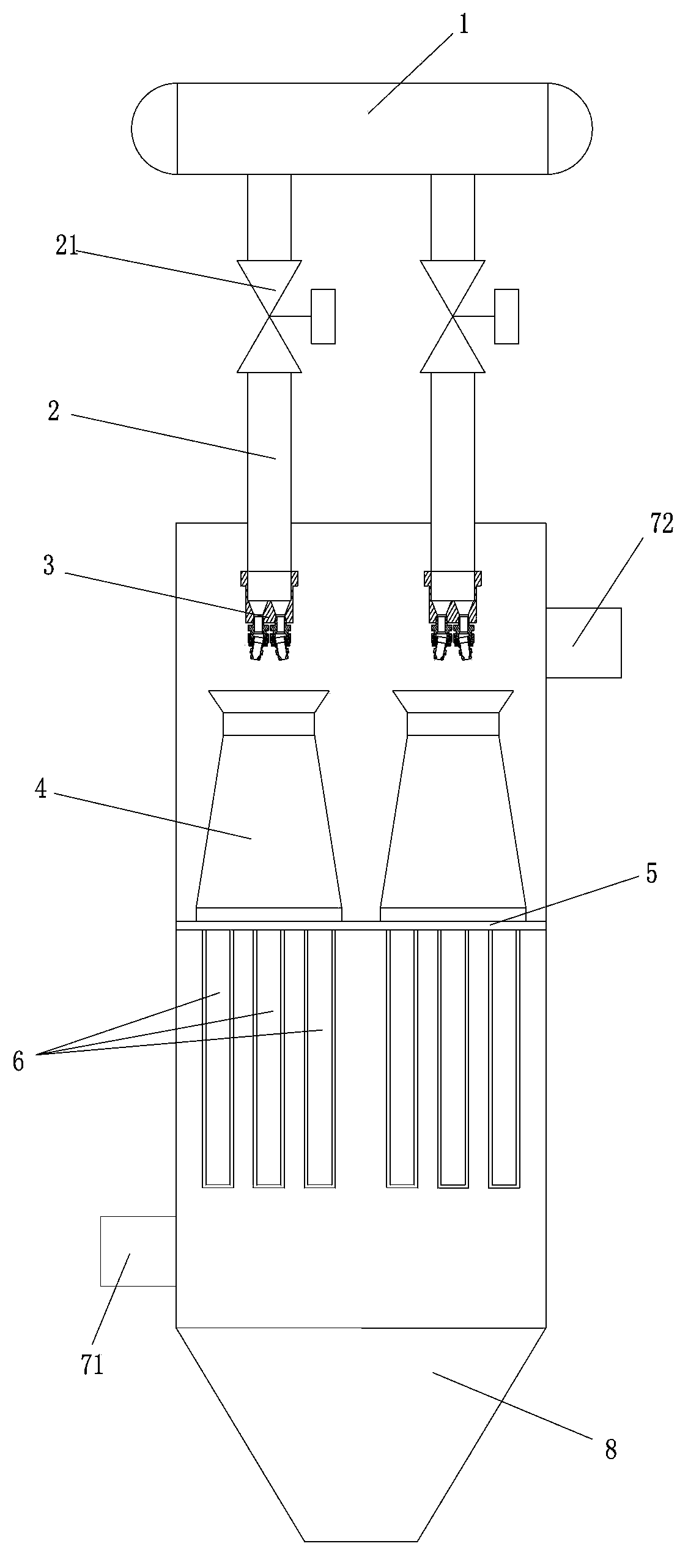
[0041] The present invention proposes a pulse back-blowing dust-cleaning device for a filter, such as figure 1 , figure 2 As shown, the tube plate 5 of the filter is provided with a filter unit. In this embodiment, the tube plate is provided with multiple sets of filter units, and each set of filter units is provided with a plurality of filter tubes 6; the filter The tube sheet 5 seals and divides the filter into an upper clean gas chamber and a lower dust-laden gas chamber, and the dust-laden gas enters the dust-laden gas chamber of the filter through the gas inlet 71 of the filter, and the particles in the air flow are intercepted On the outer surface of the filter tube 6, a powder cake layer is formed. After the gas is filt...


PUM

PropertyMeasurementUnit
separationaaaaaaaaaa

Abstract

The invention discloses a pulse backflush deashing device for a filter. Filtering units are arranged on a pipe plate of the filter, and the pipe plate divides the filter into a clean gas cavity and a dusty gas cavity in a sealing manner. The pulse backflush deashing device comprises ejectors arranged at the upper parts of the filtering units, and backflush pipelines matched with the ejectors, wherein one end of each backflush pipeline is communicated with a backflush gas storage tank through a pulse backflush valve, and a direction-adjusting multi-hole jet nozzle according to the top part of each ejector is arranged at the other end of each backflush pipeline. As the pulse backflush deashing device adopts the direction-adjusting multi-hole jet nozzles with the jet directions being adjustable, the jet direction of backflush gas can be adjusted, the jet length can be extended, and a primary jet flow and a secondary jet flow are mixed uniformly by multiple high speed jet flows, so that the distribution statuses of backflush gas flows entering the ejectors can be improved, the diffusion loss is reduced, the energy transmission efficiency can be improved, and the deficiencies, such as non-uniformity of pulse backflush, as well as gas flow eccentricity and filter pipe vibration that are brought by the existing jet nozzles, are overcome.

Description

technical field [0001] The invention relates to a gas-solid separation device, relates to a pulse back-blowing and dust-cleaning device for a filter, in particular to a pulse back-blowing and dust-cleaning device with a direction-adjustable porous jet nozzle. Background technique [0002] In chemical industry, petroleum, metallurgy, electric power and other industries, high-temperature dust-containing gases are often produced; because different processes need to recover energy and meet environmental protection emission standards, these high-temperature dust-containing gases need to be dedusted. High-temperature gas dedusting is a technology that directly separates gas from solid under high-temperature conditions to achieve gas purification. It can maximize the use of physical sensible heat, chemical latent heat and kinetic energy of the gas to improve energy utilization, while simplifying the process and saving equipment investment. [0003] Among the clean coal technologie...

Claims


Application Information

Patent Timeline
Patent Type & Authority Patents(China)
IPC IPC(8): B01D46/24B01D46/42
Inventor 姬忠礼杨亮吴小林陈鸿海赖通
Owner CHINA UNIV OF PETROLEUM (BEIJING)
Why Eureka
Try Eureka