Sintering fuel gas desulfurization and denitrification system and method

A technology for sintering flue gas, desulfurization and denitrification, which is applied in separation methods, chemical instruments and methods, dispersed particle separation, etc., can solve the problems of unreachable and unsatisfactory sintering flue gas treatment systems, high construction costs, and achieve cost reduction. Effect

Inactive Publication Date: 2013-02-06
ANGANG STEEL CO LTD
View PDF8 Cites 18 Cited by
  • Summary
  • Abstract
  • Description
  • Claims
  • Application Information

AI Technical Summary

Problems solved by technology

However, this reaction needs to be carried out under the condition that the flue gas temperature reaches 350°C-450°C, and the temperature range after sintering flue gas desulfurization is between 70°C-110°C, which does not meet the requirements of the paten...

Method used


Image

  • Sintering fuel gas desulfurization and denitrification system and method
  • Sintering fuel gas desulfurization and denitrification system and method
  • Sintering fuel gas desulfurization and denitrification system and method

Examples


Embodiment Construction

[0024] The present invention will be further described below in conjunction with accompanying drawing:

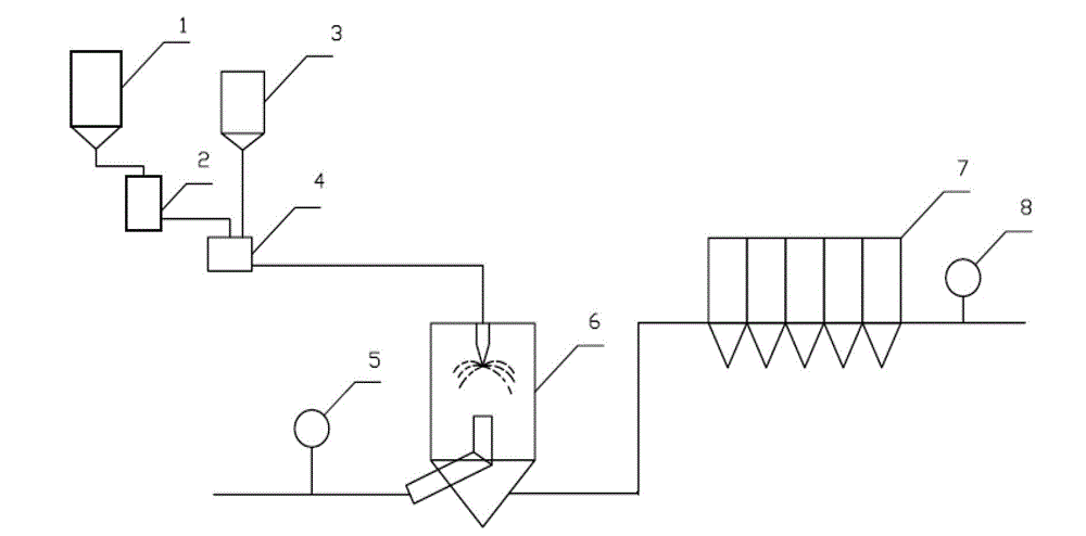
[0025] Such as figure 1 As shown, the sintering flue gas desulfurization and denitrification system includes CaO tank 1, CaO digestion tank 2, oxidant tank 3, slurry tank 4, inlet flue gas monitoring equipment 5, rotary spray absorption tower 6, bag filter 7, and outlet flue gas monitoring equipment8.

[0026] The sintering flue gas enters the rotary spray absorption tower 6, and the rotary spray absorption tower 6 is respectively connected to the slurry tank 4 and the bag filter 7, and the slurry tank 4 is connected to the CaO digestion tank 2 and the oxidant tank 3 respectively, and there is an outlet in the pipeline behind the bag filter 7 Smoke monitoring equipment8. The pipeline before the rotary spray absorption tower 6 is provided with inlet flue gas monitoring equipment 5 .

[0027] The method of sintering flue gas desulfurization and denitrification, the CaO pow...


PUM


Abstract

The invention discloses a sintering fuel gas desulfurization and denitrification system which comprises a CaO tank, a CaO digestion tank, an oxidant tank, a size tank, an inlet fuel gas monitoring device, a rotary atomization absorption tower, a cloth bag dust remover and an outlet fuel gas monitoring device. Sintering fuel gas enters the rotary atomization absorption tower. The rotary atomization absorption tower is respectively connected with the size tank and the cloth bag dust remover. The size tank is respectively connected with the CaO digestion tank and the oxidant tank. CaO powder in the CaO tank is digested after entering the CaO digestion tank and then enters the size tank after being mixed with oxidant in the oxidant tank. The mass of the oxidant counts for 1%-5% of CaO. The oxidant is a mixture of NaOH and any one of Ca(ClO)2, NaClO2, KMnO4 and H2O2. The mixing ratio is equal to the mass ratio of 1:4-1:12. The mixed liquid enters the rotary atomization absorption tower from the size tank. The atomized liquid drops are completely mixed, contacted and reacted with the sintering fuel gas entering the rotary atomization absorption tower. The reacted fuel gas is discharged after entering the cloth bag dust remover.

Description

technical field [0001] The invention belongs to the technical field of environmental protection for industrial flue gas desulfurization and denitrification, and in particular relates to a sintering flue gas desulfurization and denitrification system and a desulfurization and denitrification method thereof. Background technique [0002] In the "Twelfth Five-Year Plan", my country has clearly defined the comprehensive control of nitrogen oxides (NOx). The Ministry of Environmental Protection will highlight key areas and promote the emission reduction of sulfur dioxide and nitrogen oxide projects. In the "12th Five-Year Plan" basic idea of ​​total nitrogen oxides control, it is proposed that iron and steel and industrial boilers are also important emission sources of nitrogen oxides, and the emission control of nitrogen oxides in sintering flue gas in iron and steel enterprises is the key source of control. [0003] The traditional selective catalytic reduction denitrification...

Claims


Application Information

Patent Timeline
IPC IPC(8): B01D53/78B01D53/18B01D53/60B01D46/02
Inventor 王永陈鹏袁玲王飞胡绍伟徐伟
Owner ANGANG STEEL CO LTD
Why Eureka
Try Eureka