Pneumatic rotary tool

A technology of rotating tools and rotating mechanisms, applied in metal processing and other directions, can solve the problems of unfavorable order proofing and small batch production, low degree of automation, low cutting efficiency, etc., saving time for proofing and small batch production, and high degree of automation , The effect of good cutting quality

Inactive Publication Date: 2013-02-06
NINGBO JINGWEI SYSTEMTECHNIK LTD
View PDF9 Cites 2 Cited by
  • Summary
  • Abstract
  • Description
  • Claims
  • Application Information

AI Technical Summary

Problems solved by technology

[0002] At present, the cutting of cotton fibers, non-woven fabrics, and polyester knitted fabrics basically adopts three methods: manual cutting, cutting by a cutting machine using a knife die, and laser cutting by a laser cutting machine. All of the above three methods exist. certain defects
The disadvantage of manual cutting is that the degree of automation is low, not only the cutting efficiency is low, but also the quality of cutting depends on the technical level and proficiency of the workers; the disadvantage of cutting on the cutting machine is that it is necessary to remake the knife mold to complete the cutting of special-shaped materials, which is not conducive to the order Proofing and small batch production; the disadvantage of laser cutting is that it is easy to burn the cut edge of the fiber because it is cut by localized heat fusion

Method used


Image

  • Pneumatic rotary tool
  • Pneumatic rotary tool
  • Pneumatic rotary tool

Examples


Embodiment Construction

[0024] The present invention will be further described in detail below in conjunction with the accompanying drawings and embodiments.

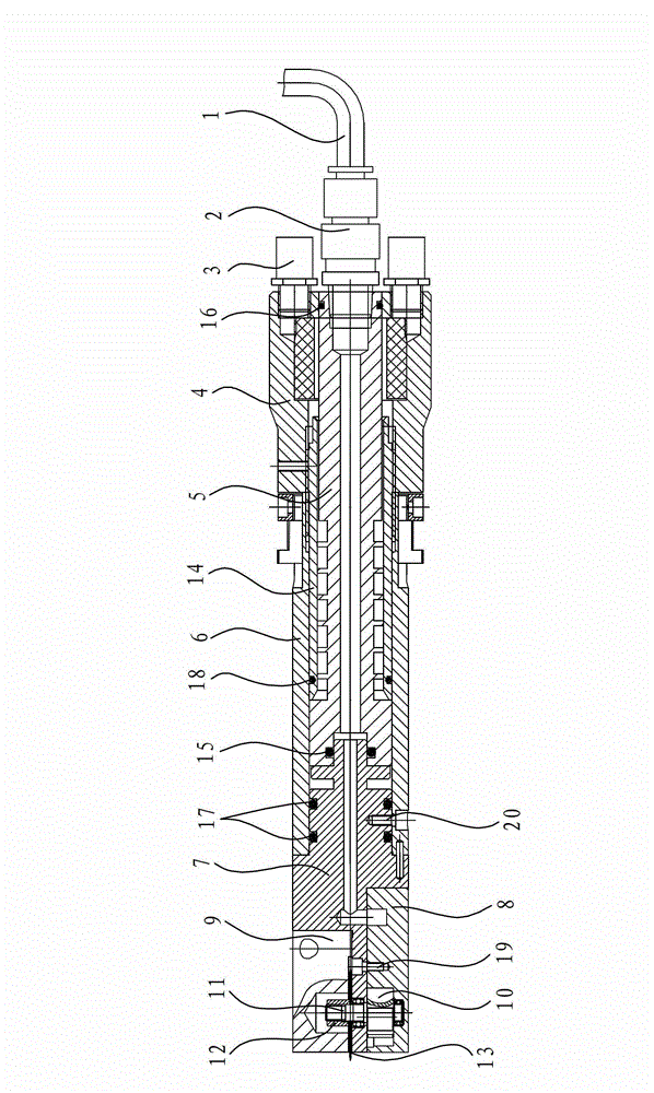
[0025] Such as Figure 1 to Figure 10 As shown, the pneumatic rotary tool in this embodiment includes a compressed air delivery mechanism, a rotary mechanism, and a tool assembly, wherein the compressed air delivery mechanism inputs compressed air to the rotary mechanism and drives the rotary parts of the rotary mechanism to rotate. After the rotary parts rotate, The cutter in the cutter assembly is driven to rotate to realize the cutting of the material. specifically,

[0026] The air delivery mechanism includes an air intake pipe 1, an air pipe joint 2, an air intake shaft 5, an air outlet shaft 14, a motor base 7 and a motor stator 8, and the air pipe joint 2 is connected between the air intake pipe 1 and the air intake shaft 5 so that the compressed air flows from the air intake The air pipe 1 is sent into the air intake end of the air i...


PUM


Abstract

The invention discloses a pneumatic rotary tool, which comprises a compressed air conveying mechanism, a rotating mechanism for carrying out rotary movement under the action of compressed air output by the conveying mechanism, and a tool subassembly for carrying out rotary cutting movement under the action of the rotating mechanism. The pneumatic rotary tool is characterized in that the air conveying mechanism comprises an air inlet pipe, an air pipe joint, an air inlet shaft, an air outlet shaft, a motor base and a motor stator, which are orderly connected and form an air conveying channel, and the rotating mechanism comprises a motor shaft and a blade, and the blade and the motor shaft carry out rotary movement under the action of the compressed air so as to drive a tool to carry out rotary cutting movement. The pneumatic rotary tool has the advantages that: firstly, the defects on the technical level and proficiency of a worker are overcome; secondly, the condition that a cutting die for a cutting bed cuts the profile shape is overcome by matching with software of a cutter; the profiling and small-batch production time in the clothing industry is effectively saved, and finally, the phenomenon of charring of the cutting edge when the laser cutter cuts fibers and non-woven fabrics by a laser is overcome because a circular knife is adopted to cut.

Description

technical field [0001] The invention relates to a cutting tool, specifically a pneumatic rotary tool, which is suitable for cutting cotton fibers, non-woven fabrics, polyester knitted fabrics, advertising materials and other materials. Background technique [0002] At present, the cutting of cotton fibers, non-woven fabrics, and polyester knitted fabrics basically adopts three methods: manual cutting, cutting by a cutting machine using a knife die, and laser cutting by a laser cutting machine. All of the above three methods exist. Certain flaws. The disadvantage of manual cutting is that the degree of automation is low, not only the cutting efficiency is low, but also the quality of cutting depends on the technical level and proficiency of the workers; the disadvantage of cutting on the cutting machine is that it is necessary to remake the knife mold to complete the cutting of special-shaped materials, which is not conducive to the order Proofing and small batch production;...

Claims


Application Information

Patent Timeline
Patent Type & Authority Applications(China)
IPC IPC(8): B26D1/14B26D5/12
Inventor 林立雪
Owner NINGBO JINGWEI SYSTEMTECHNIK LTD
Why Eureka
Try Eureka