Overhead feeding device for crane

A feeding device and crane technology, applied in the field of feeding vehicles, can solve the problems of uneven feeding, large workshop environment pollution, dust overflow, etc., and achieve the effect of ensuring smoothness and stability, good automatic control performance, and improved work efficiency.

Inactive Publication Date: 2013-02-06
新乡市起重机厂有限公司
View PDF5 Cites 1 Cited by
  • Summary
  • Abstract
  • Description
  • Claims
  • Application Information

AI Technical Summary

Problems solved by technology

[0002] At present, the cranes used in industrial production are all equipped with feeding trucks, relying on mechanical power to complete the feeding work, saving time and effort, and reducing the labor intensity of workers. However, due to their structural reasons, conventional feeding trucks have the following disadvantages: 1. During the feeding process, the dust overflows into the workshop, causing great environmental pollution; 2. The feeding is uneven, which may easily cause large pieces of material to block the outlet of the feeding tank. Once a blockage occurs, it must be shut down for maintenance. The position of the feeding car is relatively high, so it is inconvenient for maintenance; third, the material is easily bonded to the inner wall of the discharge port, and the bonding time process also leads to blockage. The conventional method is: the operator goes to the high Hit the box wall with a hammer, which is not only inefficient, but also some larger adhesives are difficult to knock off, and it will also cause damage to the box wall when the force is large.
Therefore, due to the above reasons, the equipment is very inconvenient to use, has low efficiency, and has a high damage rate, and at the same time pollutes the workshop environment relatively

Method used


Image

  • Overhead feeding device for crane
  • Overhead feeding device for crane
  • Overhead feeding device for crane

Examples


Embodiment Construction

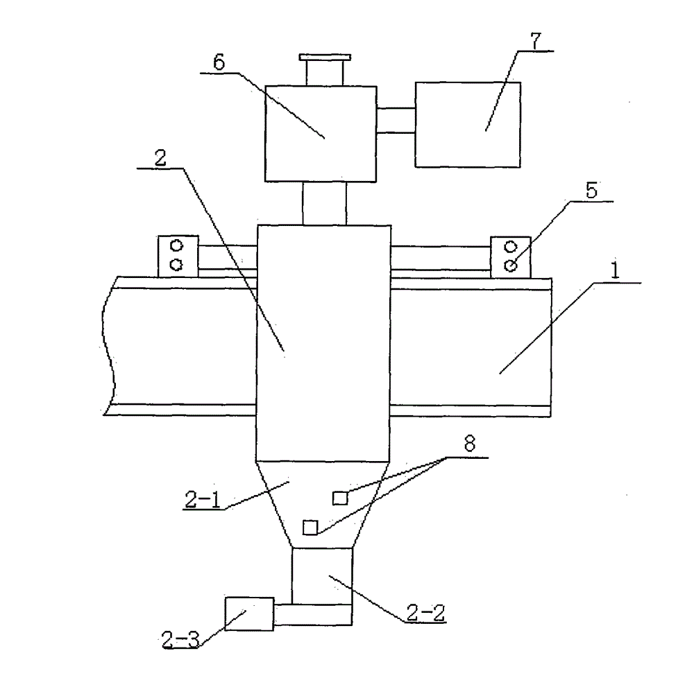
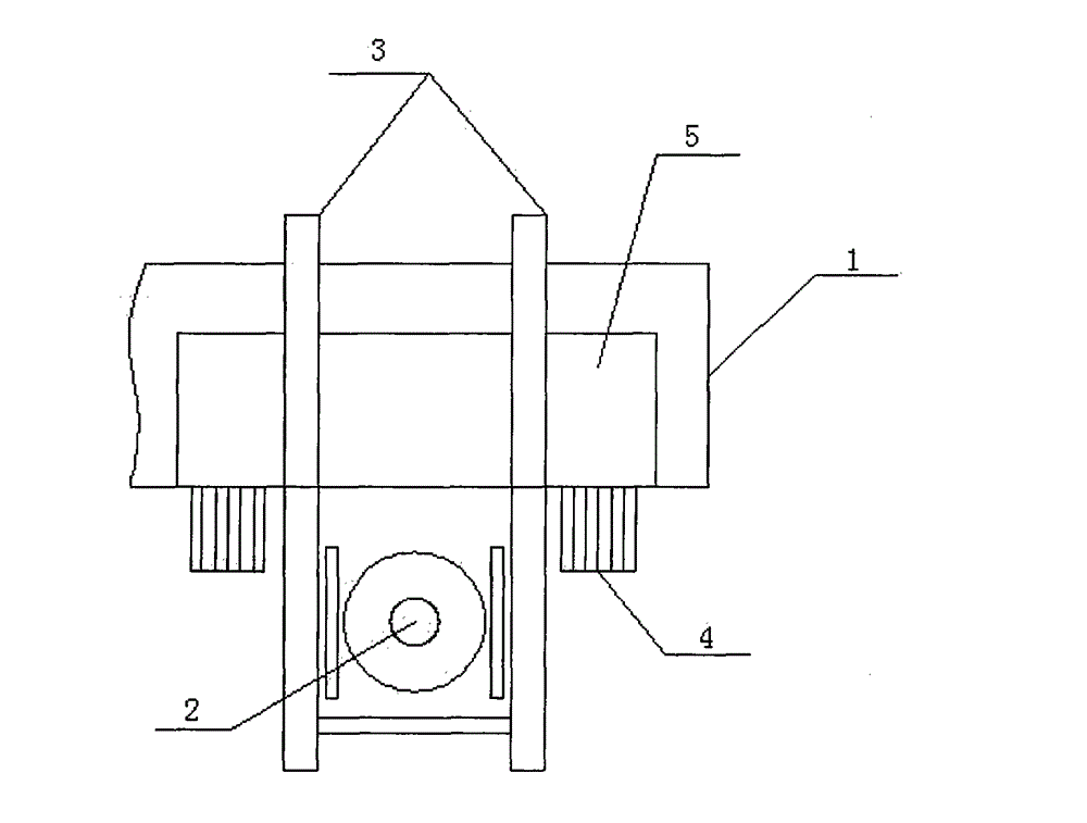
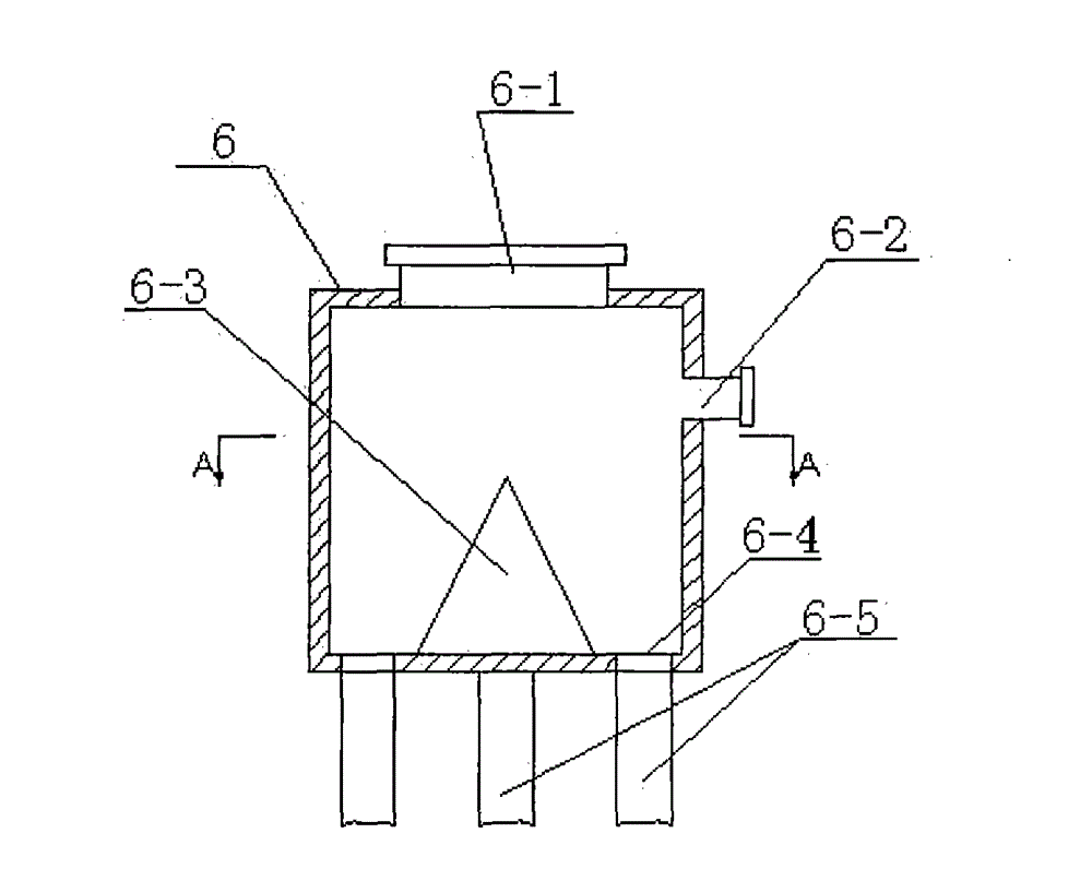
[0016] As shown in the figure, the aerial feeding device for the crane includes the frame 1, the feeding tank 2, the bracket 3, the driving mechanism 4 and the control system of the crane. Two brackets 3 parallel to each other are provided on the frame 1. One end of the bracket 3 is fixedly arranged on the support frame 5. The walking wheels at the bottom of the support frame 5 are arranged in the track groove of the frame 1, the feeding tank 2 is arranged between the two brackets 3, and the driving mechanism 4 drives the support frame 5. Horizontally reciprocating on the frame 1, a collecting box 6 and a dust collecting box 7 are provided above the feeding tank 2, and a circular feeding port 6-1 and a dust overflow port 6 are provided on the collecting box 6 2. The dust overflow port 6-2 is connected to the inlet of the dust collection box 7 through a pipeline, and a cone-shaped material dividing block 6-3 is arranged in the box body of the collecting box 6 The tip of -3 corre...


PUM


Abstract

The invention discloses an overhead feeding device for a crane. The overhead feeding device comprises a rack of the crane, a feeding tank, brackets, driving mechanisms and a control system, wherein two mutually parallel brackets are arranged on the rack, one ends of the brackets are fixedly arranged on a supporting frame, walking wheels at the bottom of the supporting frame are arranged in a rail groove of the rack, the feeding tank is arranged between the two brackets, the driving mechanisms drive the supporting frame to horizontally reciprocate on the rack, a material collection box and a dust collection box are arranged above the feeding tank, a circular feed opening and a dust overflow opening are arranged on the material collection box, the dust overflow opening is hermetically connected with the inlet of the dust collection box through a pipeline, a conical material distribution block is arranged in the box body of the material collection box, the pointed part of the material distribution block corresponds to the circle centre of the feed opening, a plurality of discharge openings are arranged at positions located at the bottom of the material collection box at the circumference of the material distribution block, and the discharge openings are hermetically connected with the inlet of the feeding tank through material guide pipes; and the device is good in automatic control performance, high in utilization rate and small in environmental pollution during the application process.

Description

Technical field [0001] The invention relates to a feeding vehicle for crane equipment, in particular to an aerial feeding device for cranes. Background technique [0002] At present, all cranes used in industrial production are equipped with a feeding truck, which relies on mechanical power to complete the feeding work, which saves time and effort, and reduces labor intensity of workers. However, due to its structure, the conventional feeding truck has the following disadvantages: 1. Dust overflows into the workshop during the feeding process, which will pollute the environment; 2. The uneven feeding will easily cause large pieces of material to block the outlet of the feeding tank. Once the clogging problem occurs, it must be shut down for maintenance. The position of the feeding cart is higher, which brings inconvenience to the maintenance; third, the material is easily bonded to the inner wall of the discharge port, and the bonding time process also causes blockage. The conven...

Claims


Application Information

Patent Timeline
Patent Type & Authority Applications(China)
IPC IPC(8): B65G65/32B65G69/18B65G69/10
Inventor 唐敦硕徐向伟王亮张占平赵海峰刘超杰逯昌鑫王永孙向龙郝峰
Owner 新乡市起重机厂有限公司
Why Eureka
Try Eureka