Construction method of bored pile

A technology of bored piles and construction methods, which is applied to sheet pile walls, foundation structure engineering, construction, etc., can solve the problems of increasing construction costs, increasing construction procedures, and low drilling efficiency, so as to save construction costs and improve The effect of drilling efficiency and simplification of construction steps

Active Publication Date: 2015-06-10
MCC COMM CONSTR GRP CO LTD
View PDF5 Cites 1 Cited by
  • Summary
  • Abstract
  • Description
  • Claims
  • Application Information

AI Technical Summary

Problems solved by technology

[0003] The disadvantage of this method is that, first of all, since the casing 2 and the traditional drilling machine 0 are constructed separately, it not only increases the construction process, but also needs to stop the drilling constantly, check the verticality of the pile body, and avoid pile hole deviation or inclined hole ; Secondly, the traditional drilling rigs used at this stage use cutting and grinding methods to process rocks. For hard pebble layers or complex formations, the drilling efficiency is low, and the drill bits are severely worn; finally, the existing construction methods use mud for multiple steps. The technology not only increases the construction cost, but also the viscosity, relative density, sand content and other parameters of the mud need to be changed according to various factors such as the rock formation, which has high requirements for the technical level of mud preparation

Method used


Image

  • Construction method of bored pile
  • Construction method of bored pile
  • Construction method of bored pile

Examples


Embodiment Construction

[0015] Embodiments of the construction method of the bored pile according to the present invention will be described below with reference to the accompanying drawings. As those skilled in the art would realize, the described embodiments may be modified in various different ways, all without departing from the spirit and scope of the present invention. Accordingly, the drawings and description are illustrative in nature and not intended to limit the scope of the claims. In addition, in this specification, the same reference numerals denote the same or similar parts.

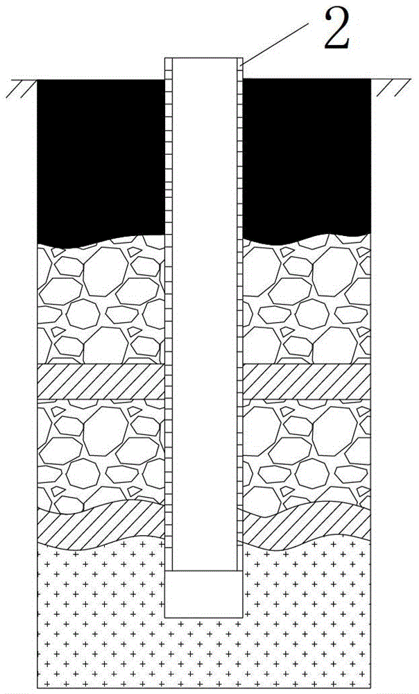
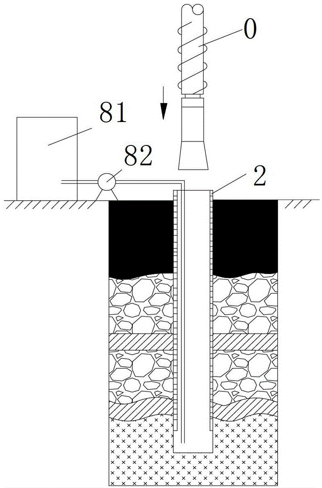
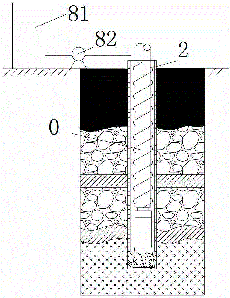
[0016] figure 2 It shows the construction flowchart of the bored pile described in one embodiment of the present invention. Such as figure 2 As shown, the construction process of the bored cast-in-place pile of the present invention is as follows: first, the first step S100 is to locate the position of the bored cast-in-place pile according to the design requirements, install the drilling rig 1, connect the t...


PUM


Abstract

The invention provides a construction method of a bored pile. The construction method of the bored pile comprises the following steps: a), fixing a pile position, assembling a boring machine, connecting the bottom end of a threaded boring rod and a combined down-the-hole hammer, and fixing the boring machine at the pile position; moving a pile casing to a position above the boring machine, combining the pile casing above the bottom end of the combined down-the-hole hammer through the threaded boring rod, and superposing the pile casing with the boring machine axially; b), connecting a boring machine power head and the boring machine and driving the boring machine to rotate, connecting a pile casing power head and the pile casing and driving the pile casing to rotate, and making the rotating directions of the boring machine and the pile casing opposite; starting up the boring machine power head and the pile casing power head at the same time so that a boring head and the pile casing at the same time vertically bore downwards; c), boring to a designed bore depth, moving the boring machine out of a pile bore, and installing a reinforcement cage into the pile casing; d), installing a grouting pipe above the reinforcement cage, and pouring concrete into the pile casing through the grouting pipe; and e), after pouring, pulling out the pile casing, and solidifying and molding the bored pile. By the construction method of the bored pile, construction steps are reduced; and the environment pollution is avoided because a mud process is not adopted. Therefore, the construction method of the bored pile is high in efficiency.

Description

technical field [0001] The invention relates to the construction field, in particular to a construction method of bored cast-in-place piles. Background technique [0002] In building foundation engineering, with the continuous development of pile machinery for hole-forming operations, bored piles are widely used in foundation construction projects such as high-rise buildings, highway bridges and large structures. Figures 1a-1f The construction method of the existing bored pile is shown. Such as Figure 1a As shown, according to the design requirements, locate the pile position and bury the casing 2. Such as Figure 1b Shown, at first, fix traditional drilling rig 0 on pile position; Then, prepare mud by mud preparation equipment 81; As Figure 1c As shown, the mud is transported into the casing 2 by the mud conveying equipment 82, and the traditional drilling rig 0 drills vertically downward until the required depth is reached; Figure 1d As shown, the traditional drill...

Claims


Application Information

Patent Timeline
Patent Type & Authority Patents(China)
IPC IPC(8): E02D5/38
Inventor 肖剑刘锋
Owner MCC COMM CONSTR GRP CO LTD
Why Eureka
Try Eureka