Engine hydraulic energy and power conversion device

A power conversion and engine technology, applied in the direction of machines/engines, mechanical equipment, etc., can solve the problems of poor power transmission reliability, poor ignition stability, unfixed top dead center, etc., and achieve high-efficiency power conversion within the machine, fast power transmission, and principle reliable effect

Inactive Publication Date: 2013-02-06
QINGDAO UNIV
View PDF4 Cites 7 Cited by
  • Summary
  • Abstract
  • Description
  • Claims
  • Application Information

AI Technical Summary

Problems solved by technology

But because the hydraulic free piston engine has problems such as unstable top dead center and poor ignition stability, it has been difficult to be popularized and used; although other similar types of engines can solve the problems existing in the free piston engine, they have poor power transmission reliability, mechanical How to comprehensively realize the high efficiency and working reliability of the engine hydraulic energy and power conversion will be the key issue of the engine structure improvement technology. The multi-link structure is adopted to realize the efficient internal conversion of power and the reliability of the force. The transfer process is an innovative technical issue being discussed by scientific and technical personnel in the industry

Method used


Image

  • Engine hydraulic energy and power conversion device
  • Engine hydraulic energy and power conversion device

Examples


Embodiment Construction

[0009] Further description will be given below through the embodiments and in conjunction with the accompanying drawings.

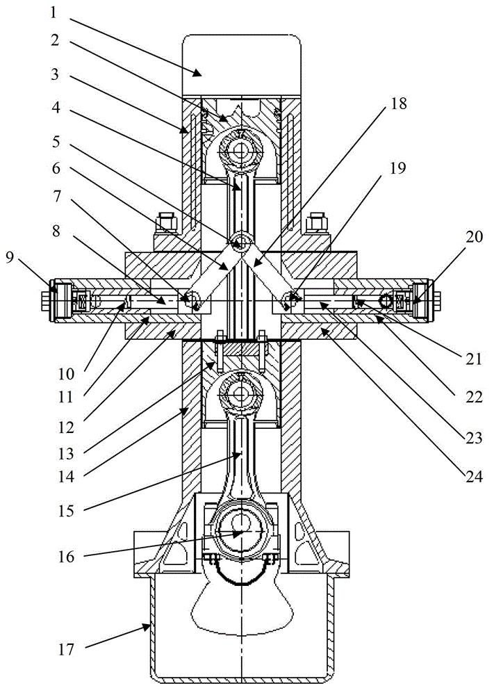
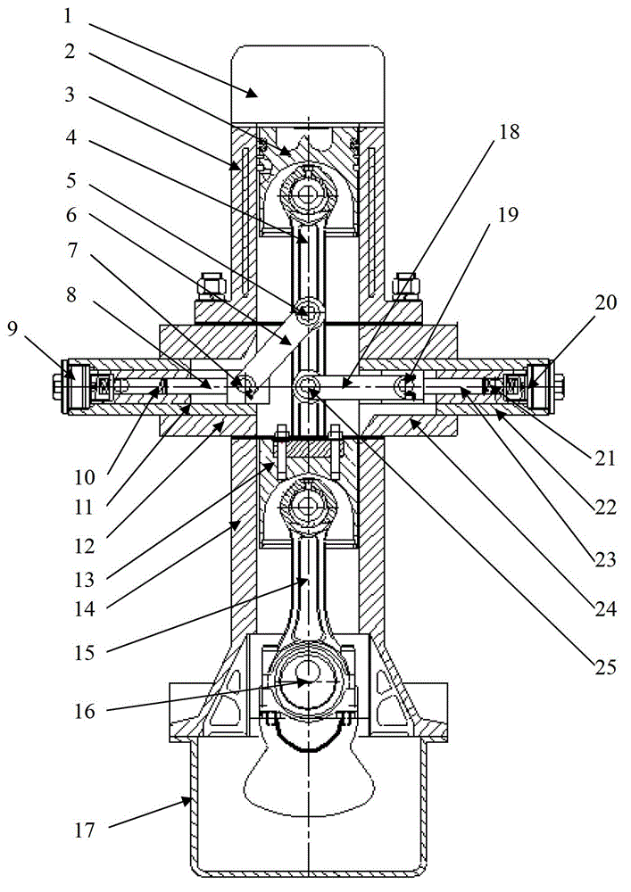
[0010] The main structure of this embodiment includes a cylinder head 1, a working piston 2, a cylinder block 3, an upper connecting rod 4, a first, a bifurcated rod pin 5 and 25, a first, a bifurcated rod 6 and 18, a first , two plunger connecting pins 7 and 19, the first and second plunger pumps 9 and 20, the first and second plungers 8 and 23, the first and second plunger springs 10 and 21, the first and second pump bodies 11 and 22. First and second pump seats 12 and 24, guide piston 13, lower body 14, connecting rod 15, crankshaft 16 and oil pan 17; composed of cylinder head 1, cylinder block 3, lower body 14 and oil pan 17 The body assembly, the cylinder block 3 and the lower body 14 are made into an integrated structure, just like the cylinder head 1 of a traditional engine is installed on the cylinder block 3; the oil pan 17 is fixedly installed o...


PUM


Abstract

The invention belongs to the technical field of internal-combustion engine energy conversion, and relates to an engine hydraulic energy and power conversion device. The engine hydraulic energy and power conversion device is characterized in that an oil pan is fixedly arranged on a crank shaft box of a lower machine body, first and second pump bases are respectively fixedly arranged between an air cylinder body and the lower machine body, and the two pump bases are symmetrically arranged on the two sides of a machine body; a working piston, an upper connecting rod, a guide piston and a connecting rod are connected to form a piston connecting rod assembly, and the guide piston is articulated on a small head of the connecting rod; a large head of the connecting rod is connected with a crank pin of a crank shaft, first and second plunger pumps are fixedly arranged between the first and second pump bases, drivers of the two plunger pumps are articulated on a first forked lever pin shaft of the upper connecting rod so as to form a symmetrical drive structure, or, drivers of the two plunger pumps are articulated on the first and second fork rods on the different positions of the upper connecting rods so as to form an asymmetric driving structure; and the crank shaft is fixedly arranged in a crank shaft hole in the lower machine body. The engine hydraulic energy and power conversion device provided by the invention has the advantages that the structure is simple, a principle is reliable, the energy utilization efficient is high, the cost is saved, the power transmission is rapid, and the device is environment-friendly.

Description

Technical field: [0001] The invention belongs to the technical field of internal combustion engine energy conversion, and relates to a structure for internal energy conversion of an engine, in particular to an engine hydraulic energy and power conversion device. Background technique: [0002] At present, for reciprocating engines, in order to improve the efficiency of power machinery, it is necessary not only to improve the effective efficiency of the engine, but also to tap the potential of improving the comprehensive efficiency of power machinery; the hydraulic free piston engine is a good example. But because the hydraulic free piston engine has problems such as unstable top dead center and poor ignition stability, it has been difficult to be popularized and used; although other similar types of engines can solve the problems existing in the free piston engine, they have poor power transmission reliability, mechanical How to comprehensively realize the high efficiency and...

Claims


Application Information

Patent Timeline
Patent Type & Authority Applications(China)
IPC IPC(8): F02B75/32
Inventor 张纪鹏张铁柱张风太邹荣国程联军马永志霍炜张继忠
Owner QINGDAO UNIV
Why Eureka
Try Eureka