[0024] It should be noted that the embodiments of the present invention and the features in the embodiments can be combined with each other if there is no conflict. Hereinafter, the present invention will be described in detail with reference to the drawings and in conjunction with the embodiments.
[0025] The basic idea of the present invention is to solve the problem of uncontrollable EGR gas temperature. The present invention provides an EGR gas temperature control device, which adds a bypass pipe to the passage of the EGR cooler coolant, and cools the inside of the bypass pipe. The flow rate of the liquid is used to adjust the flow rate of the coolant in the EGR cooler to control the temperature of the EGR gas within the required range.
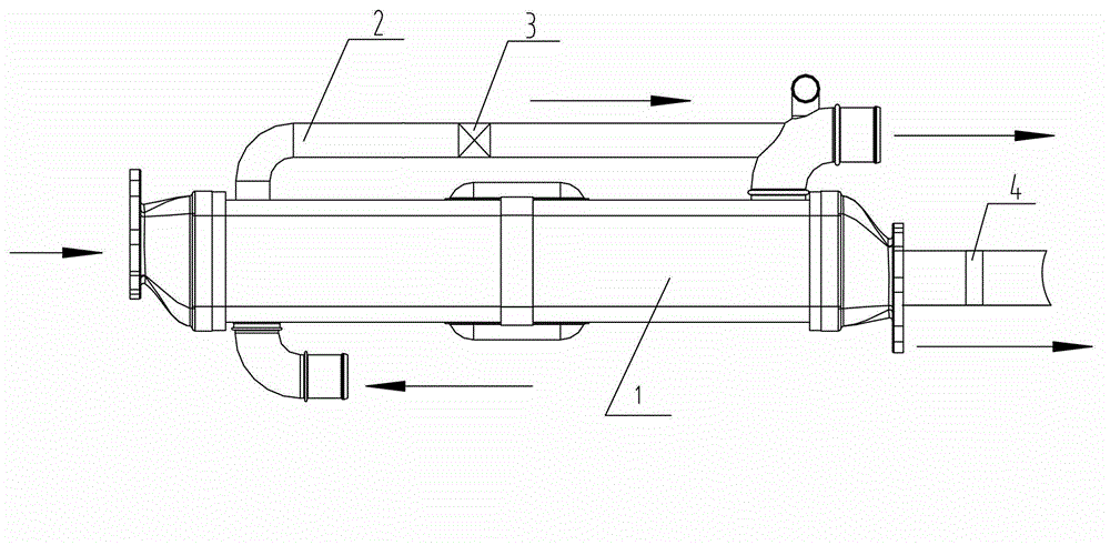
[0026] Combine below figure 1 , The preferred embodiment of the present invention will be described in further detail: the EGR gas temperature control device includes: an EGR cooler 1 for cooling the EGR gas introduced from the engine exhaust pipe; a bypass pipe 2, the inlet of which is connected to the EGR cooler 1 The coolant inlet is connected; the flow regulating valve 3 is installed on the bypass pipe 2 to adjust the flow of the coolant in the bypass pipe 2.
[0027] In the above solution, when the temperature of the EGR gas needs to be lowered, the opening degree of the flow regulating valve 3 is reduced to reduce the flow rate of the coolant in the bypass pipe 2. Since the sum of the coolant flow rate in the bypass pipe 2 and the EGR cooler 1 is constant, the flow rate of the coolant in the bypass pipe 2 is reduced, and the coolant flow rate in the EGR cooler 1 is increased at the same time. The cooling capacity of the cooler 1 is enhanced, and the temperature of the EGR gas is lowered.
[0028] When it is necessary to increase the EGR gas temperature, increase the opening of the flow control valve 3 to increase the flow rate of the coolant in the bypass pipe 2 and decrease the flow rate of the coolant in the EGR cooler 1, and the cooling capacity of the EGR cooler 1 Decrease, the temperature of EGR gas rises.
[0029] In this solution, the temperature of the EGR gas can be controlled by adjusting the opening degree of the flow regulating valve 3. The control structure is simple and the operation is simple.
[0030] Further, a temperature sensor 4 is installed on the gas outlet pipe of the EGR cooler 1. In this way, the actual temperature of the EGR gas can be detected in real time, so that the actual temperature can be compared with the target temperature, and the opening of the regulating valve 3 can be adjusted according to the comparison result, so that the actual temperature of the EGR gas can be adjusted to the target temperature value, so that the EGR gas The temperature control is more accurate. The above-mentioned target temperature is the optimal temperature of the engine EGR, and the target temperature can be obtained through experiments and set in the control system. The control system may be a part of the engine control system or a control system separately provided for the EGR system.
[0031] Further, the flow regulating valve 3 is a flow solenoid valve, a motor-driven valve, or an electronic thermostat. Flow solenoid valves, motor-driven valves or electronic thermostats can be controlled by electronic control signals, so that the control system can send control signals to adjust the opening of the flow control valve 3, thereby realizing automatic control of the EGR gas temperature. The automatic control process is as follows: first detect the actual temperature of the EGR gas through the temperature sensor 4, the control system compares the actual temperature of the EGR gas with the target temperature, and then sends a control signal to the flow control valve 3 to adjust its opening according to the comparison result. Adjust the actual temperature of the EGR gas to the target temperature value.
[0032] Further, the EGR gas temperature control device matches the EGR cooler 1 with a corresponding cooling capacity according to the maximum EGR rate and the maximum exhaust temperature of the engine. The above-mentioned EGR ratio is the ratio of the mass of EGR gas to the mass of mixed gas burned by the engine. The higher the EGR rate, the more EGR gas that passes through the EGR cooler 1, and the higher the cooling capacity of the EGR cooler 1 is required. The engine exhaust temperature is the temperature of the EGR gas before cooling. The higher the temperature, the higher the cooling capacity of the EGR cooler 1 is required. Adjusting the flow rate of the bypass pipe 2 can reduce the cooling capacity of the EGR cooler 1. Therefore, the EGR cooler 1 with the corresponding cooling capacity is matched according to the engine's maximum EGR rate and maximum exhaust temperature, which can meet the EGR gas temperature under any working conditions Regulation requirements.
[0033] Further, the outlet of the bypass pipe 2 is in communication with the coolant outlet of the EGR cooler 1. This is convenient for layout and has a more compact structure.
[0034] The present invention also provides an engine including the above-mentioned EGR gas temperature control device. Since the EGR gas temperature control device has the above-mentioned technical effects, the engine including the above-mentioned EGR gas temperature control device should also have corresponding technical effects. The implementation process is similar to the foregoing embodiment, and will not be repeated here.
[0035] The present invention also provides an engineering machine including the above-mentioned engine. Since the engine has the above-mentioned technical effects, the engineering machine including the above-mentioned engine should also have corresponding technical effects. The specific implementation process is similar to the above-mentioned embodiment and will not be repeated here.
[0036] The present invention also provides an EGR gas temperature control method, which includes the following steps:
[0037] S1, detecting the actual temperature of the EGR gas at the gas outlet of the EGR cooler 1;
[0038] S2, compare the actual temperature with the target temperature;
[0039] S3. Adjust the opening degree of the flow control valve 3 according to the comparison result, so as to adjust the coolant flow rate in the bypass pipe 2 and the coolant flow rate in the EGR cooler 1.
[0040] Steps S2 and S3 in the above method can be performed manually by comparing the two temperatures, and then manually adjusting the opening of the flow regulating valve 3; or it can be performed automatically after a program is set in the control system. The control method is simple and easy to operate, and can control the EGR gas temperature according to actual working conditions.
[0041] Further, step S1 also includes: matching the EGR cooler 1 with the corresponding cooling capacity according to the maximum EGR rate and the maximum exhaust temperature of the engine. Adjusting the flow rate of the bypass pipe 2 can reduce the cooling capacity of the EGR cooler 1. Therefore, the EGR cooler 1 with the corresponding cooling capacity is matched according to the engine's maximum EGR rate and maximum exhaust temperature, which can meet the EGR gas temperature under any working conditions Regulation requirements.
[0042] Further, step S1 also includes: setting the initial opening degree of the flow regulating valve 3 according to the EGR rate and exhaust temperature under the actual operating conditions of the engine. In this way, the EGR gas temperature can be controlled within a better temperature range, and then the opening of the flow regulating valve 3 can be adjusted according to the comparison result of the actual EGR temperature and the target temperature, so as to realize the precise control of the EGR gas temperature.
[0043] The above descriptions are only preferred embodiments of the present invention and are not intended to limit the present invention. Any modification, equivalent replacement, improvement, etc. made within the spirit and principle of the present invention shall be included in the present invention. Within the scope of protection.