
Electric control system of asynchronous wind generating set

A technology of wind turbine generator set and electric control system, applied in wind turbine combination, wind turbine control, wind turbine and other directions, can solve the problems of lack of low voltage ride-through capability, large fluctuation of reactive power, low wind energy utilization efficiency, etc. Achieve perfect high voltage ride-through capability, increase power generation, and achieve the effect of unit reactive power control

Inactive Publication Date: 2013-02-06
NANJING HIGH DRIVE ELECTROMECHANICAL AUTOMATION EQUIP CO LTD
View PDF5 Cites 17 Cited by
  • Summary
  • Abstract
  • Description
  • Claims
  • Application Information

AI Technical Summary

Problems solved by technology

[0005] The purpose of the present invention is to solve the problems of low wind energy utilization efficiency, large grid-connected impact, large reactive power fluctuations, and lack of low voltage ride-through capability existing in traditional fixed-pitch or variable-pitch constant-speed asynchronous wind power generating sets. A grid-friendly wind power system that can not only improve wind energy utilization efficiency and power generation, but also have dynamic reactive power adjustment and low-voltage ride-through

Method used

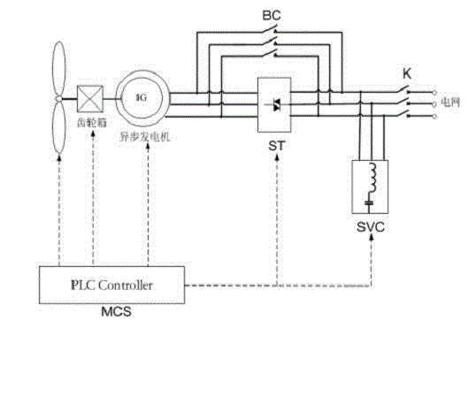

Image

  • Electric control system of asynchronous wind generating set
  • Electric control system of asynchronous wind generating set

Examples


Embodiment Construction

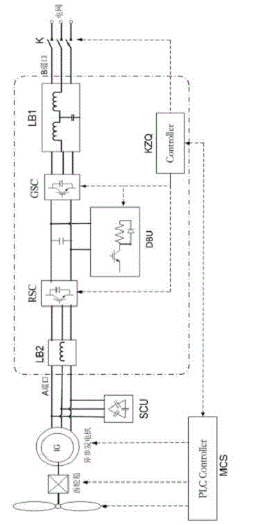
[0020] figure 2 The specific structures of the embodiments of the present invention are disclosed without limitation, and the present invention will be further described below in conjunction with the accompanying drawings.

[0021] Depend on figure 2 It can be seen that the present invention includes a main control system MCS, a full power converter, a circuit breaker K and a converter controller KZQ, wherein: the full power converter is provided with an A port and a B port, and the A port is connected to the asynchronous power generation The B port is connected to the grid through the circuit breaker K; the full power converter includes the machine-side converter RSC, the grid-side converter GSC, and the DC braking unit DBU, in which the machine-side converter RSC and The grid-side converter GSC is connected back-to-back through the common DC bus, and the DC braking unit DBU is connected to the common DC bus; both the grid-side converter and the machine-side converter are ...


PUM


Abstract

The invention relates to an electric control system of an asynchronous wind generating set. The electric control system comprises a master control system (MCS), a full power converter, a machine side self-excited capacitor unit (SCU), a breaker K and a converter controller KZQ, wherein an A port and a B port are arranged on the full power converter, the A port is connected with a stator of an asynchronous generator, and the B port is connected with a power grid through the breaker K. The full power converter comprises a ram side converter (RSC), a grid side converter (GSC) and a direct current braking unit (DBU), wherein the ram side converter (RSC) and the net side converter (GSC) are connected in a back-and-back mode through a common direct current bus, and the direct current braking unit (DBU) is connected onto the common direct current bus. A filter LB1 is arranged between an alternating current input side of the net side converter and the B port, and a filter LB2 is arranged between an alternating current input side of the ram side converter (RSC) and the A port. After the MCS obtains operation information of the asynchronous wind generating set, the converter controller KZQ is used for controlling the full power converter.

Description

technical field [0001] The invention designs an electric control system for asynchronous wind power generators, which is suitable for the transformation of fixed-pitch and constant-speed asynchronous wind power generators and variable-pitch constant-speed asynchronous wind power generators, and can also be applied to variable-pitch and variable-speed asynchronous wind power generators The technical field of power equipment control. Background technique [0002] With the continuous and rapid development of the global economy in the 21st century, energy has become a bottleneck restricting the development of energy in various countries. At the same time, due to the improvement of living standards, people pay more and more attention to the environment in which they live. energy. Among the many renewable energy sources at present, wind power is the most mature, most suitable for large-scale development, and most competitive. [0003] The main function of the wind power generati...

Claims


Application Information

Patent Timeline
Patent Type & Authority Applications(China)
IPC IPC(8): H02J3/38H02J3/46F03D9/00F03D7/00
CPCY02E10/763Y02E10/723Y02E10/72Y02E10/76
Inventor 王中廖恩荣黄晓辉李志国辛志远
Owner NANJING HIGH DRIVE ELECTROMECHANICAL AUTOMATION EQUIP CO LTD
Learn More