Dual-light beam laser welding method of K-shaped joint

A laser welding and double beam technology, applied in laser welding equipment, welding equipment, metal processing equipment, etc., can solve the problems of welding seam stress concentration, poor welding seam quality, and low welding efficiency, and reduce the welding seam stress concentration. , The effect of stable welding quality and high welding efficiency

Active Publication Date: 2015-03-04
HARBIN INST OF TECH
View PDF7 Cites 0 Cited by
  • Summary
  • Abstract
  • Description
  • Claims
  • Application Information

AI Technical Summary

Problems solved by technology

[0003] The purpose of the present invention is to provide a double-beam laser welding method for K-type joints in order to solve the problems of low welding efficiency, weld stress concentration, poor weld quality and difficult control in the existing single laser welding process

Method used


Image

  • Dual-light beam laser welding method of K-shaped joint
  • Dual-light beam laser welding method of K-shaped joint
  • Dual-light beam laser welding method of K-shaped joint

Examples


specific Embodiment approach 1

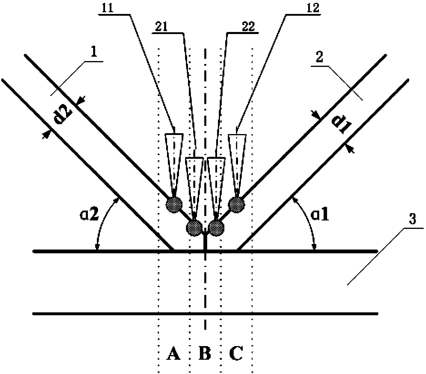
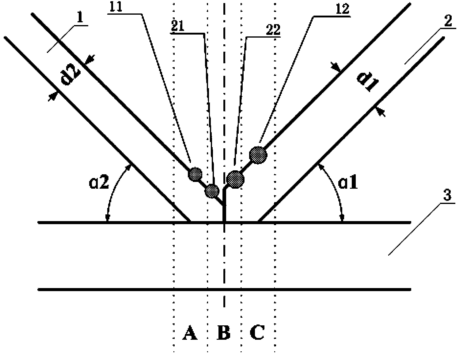
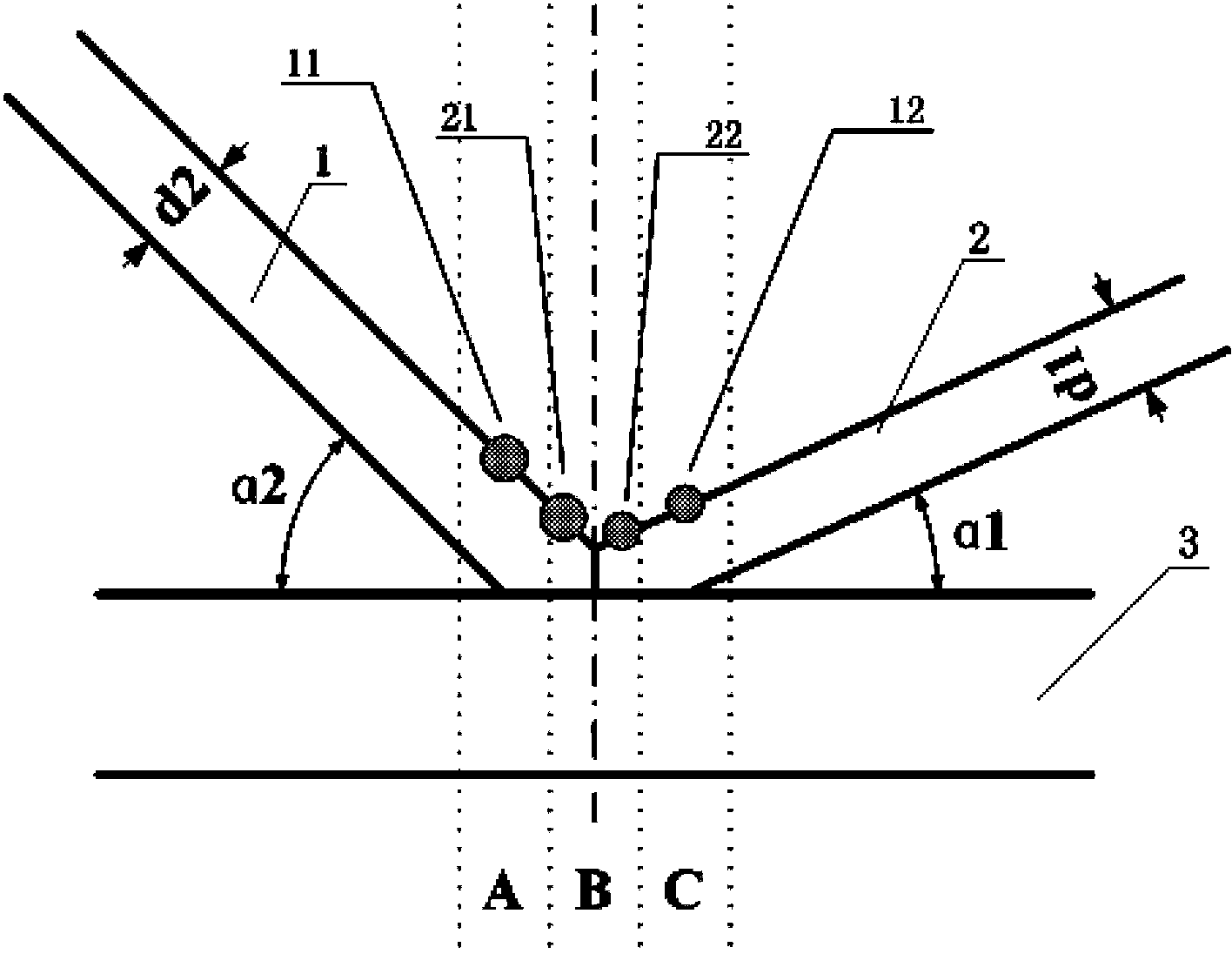
[0018] Specific embodiment one: the double-beam laser welding method of the K-type joint in this embodiment is carried out according to the following steps:

[0019] Two lasers are used to emit the main beam a and the main beam b respectively, the main beam a is divided into welding beam 11 and welding beam 12, the main beam b is divided into welding beam 21 and welding beam 22, the focusing spot of welding beam 11 and the welding beam 12 The focusing spots are arranged in parallel, the welding beam 11 acts on the boundary area A between the support plate 1 and the bottom plate 3, the welding beam 12 acts on the boundary area C between the support plate 2 and the bottom plate 3, the focusing spot of the welding beam 21 and the focusing of the welding beam 22 The spots are arranged in parallel and distributed on both sides of the interface between the support plate 1 and the support plate 2, and the welding beam 21 and the welding beam 22 act on the boundary area B between the s...

specific Embodiment approach 2

[0023] Specific embodiment two: the difference between this embodiment and specific embodiment one is that the laser is a fiber laser, Nd:YAG solid-state laser, semiconductor laser or CO 2 laser. Others are the same as in the first embodiment.

specific Embodiment approach 3

[0024] Embodiment 3: This embodiment differs from Embodiment 1 in that the spot distance δ1 between the welding beam 11 and the welding beam 12 is 4.0 mm, and the spot distance δ2 between the welding beam 21 and the welding beam 22 is 1.5 mm. Others are the same as in the first embodiment.


PUM


Abstract

The invention provides a dual-light beam laser welding method of a K-shaped joint and relates to a welding method. The invention solves the problems of low welding efficiency, concentrated weld stress, poor weld quality and uneasiness in control existing in the existing single-light beam laser welding process. The dual-light beam laser welding method comprises the following steps: respectively emitting a main light beam a and a main light beam b by applying two lasers, dividing the main light beam a into a welding light beam 11 and a welding light beam 12, dividing the main light beam b into a welding light beam 21 and a welding light beam 22, acting the welding light beam 11 in a junction area A between a support plate 1 and a bottom plate 3, acting the welding light beam 12 in a junction area C between a support plate 2 and the bottom plate 3, acting the welding light beam 21 and the welding light beam 22 in a junction area B between the support plate 1 and the support plate 2. Aiming at the characteristics of the K-shaped joint, the dual-beam laser welding method has the advantages of high welding efficiency and good and stable welding quality.

Description

technical field [0001] The present invention relates to welding methods. Background technique [0002] In the field of aerospace manufacturing, in addition to traditional butt joints, lap joints, fillet joints, end joints and T-joints, there are also special K-joints, which are also widely used in component manufacturing. Generally, aerospace components have very strict requirements on machining accuracy. Because the wall thickness of the support plate that constitutes the joint is relatively thin, traditional welding methods, such as arc welding, may easily cause local deformation of the component after welding due to the large heat input. Seriously affect the dimensional accuracy of the parts, making it difficult to meet the use requirements. Therefore, laser welding and other high-energy beam welding methods are generally used for this type of joint. However, traditional single laser welding is difficult to meet the requirements of K-type joints for welding quality and ...

Claims


Application Information

Patent Timeline
Patent Type & Authority Patents(China)
IPC IPC(8): B23K26/21B23K26/064B23K26/26
Inventor 陈彦宾马国龙李俐群陶汪章敏
Owner HARBIN INST OF TECH
Why Eureka
Try Eureka