Anoxic-aerobic vertical flow artificial wetland system

A constructed wetland system, vertical flow wetland technology, applied in aerobic and anaerobic process treatment, chemical instruments and methods, water/sludge/sewage treatment, etc.

Inactive Publication Date: 2013-02-13
SHANDONG UNIV
View PDF7 Cites 29 Cited by
  • Summary
  • Abstract
  • Description
  • Claims
  • Application Information

AI Technical Summary

Problems solved by technology

[0004] Aiming at the deficiencies of the current vertical flow constructed wetland technology, the present invention provides an anoxic-aerobic vertical flow constructed wetland treatment system with strong denitrification ability, high efficiency, small footprint and strong impact load resistance

Method used


Image

  • Anoxic-aerobic vertical flow artificial wetland system
  • Anoxic-aerobic vertical flow artificial wetland system
  • Anoxic-aerobic vertical flow artificial wetland system

Examples


Embodiment 1

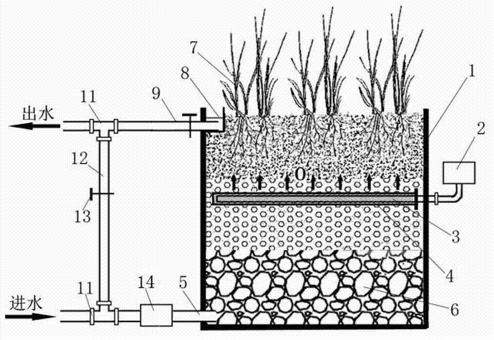
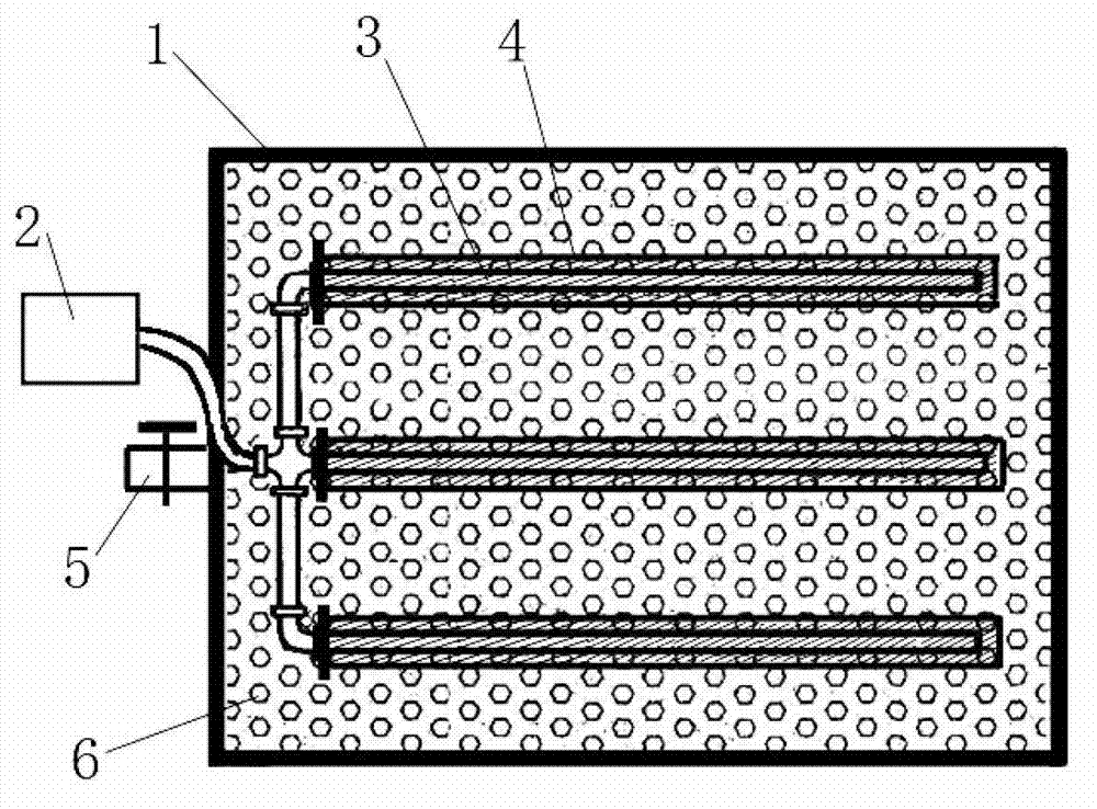
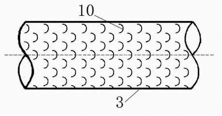
[0015] Such as figure 1 and figure 2 As shown, the anoxic-aerobic vertical flow wetland of the present invention mainly includes a wetland pool body 1, an aeration device, a water inlet pipe 5, a drain pipe 9, an outlet water return device and wetland plants 7. The four sides and the bottom of the wetland pool body 1 are treated with anti-seepage. The lower part of the wetland pool body 1 is provided with a water inlet pipe 5, and the upper part is provided with an outlet weir 8 and a drain pipe 9, and a water outlet return device composed of a tee 11, a return pipe 12, and a return valve 13 is arranged behind the drain pipe 9; the wetland pool The matrix filler 6 needs to be laid in the body 1, the particle size of the matrix filler 6 gradually decreases from bottom to top, coarse sand is laid on the top layer, the aeration device is located at 2 / 3 of the water level of the pool body, and the aeration tube 3 is covered with a protective Rigid plastic network pipe 4, the gr...

Embodiment 2

[0019] Such as Figure 4 As shown, this embodiment adopts the downstream operation mode to treat sewage. The water inlet pipe 5 is arranged at the upper part of the wetland pool body 1, the drain pipe 9 is arranged at the bottom, and the rest of the structure is basically the same as that of the first embodiment.

[0020] During operation, the sewage enters the vertical flow wetland system through the water inlet pipe 5, first enters the upper aerobic zone for nitrification reaction, then flows into the anoxic zone at the bottom of the pool body for denitrification reaction, and finally the purified sewage is discharged from the bottom drain pipe 9 Drain the pool.

Embodiment 3

[0022] Such as Figure 5 As shown, the aeration device in the present invention can also adopt an annular aeration tube, which is suitable for circular wetlands and the like.


PUM


Abstract

The invention relates to an anoxic-aerobic vertical flow artificial wetland system which comprises a wetland tank body, an aerating device, a water inlet pipe, a drain pipe, a water outflow reflux device and wetland plants. The aerating device is arranged on the upper and middle portion of a vertical flow wetland, so that the lower portion of the wetland is maintained in an anoxic state, and an aerobic zone and an anoxic zone which are required for nitrification and denitrification reactions are simultaneously formed in the vertical flow artificial wetland system. When the anoxic-aerobic vertical flow artificial wetland system runs, raw sewage first enters the vertical flow wetland tank body through the bottom water inlet pipe and a water inlet pump and passes through the anoxic zone at the bottom of the tank body, an adequate carbon source in the sewage is utilized to perform the denitrification reaction; and then the sewage enters the aerobic zone which is positioned in the middle of the tank body and provided with the aerating device, and after aeration oxygenation nitrification reaction treatment and combined action of plant root systems, finally the purified sewage is discharged out of the wetland tank body through the drain pipe on the upper portion. The artificial wetland can effectively remove pollutants, and the denitrification effect is greatly improved.

Description

1. Technical field [0001] The invention relates to an anoxic-aerobic vertical flow artificial wetland system, which belongs to the technical field of environmental engineering sewage treatment. 2. Technical background [0002] Due to the characteristics of low investment, low energy consumption, large buffer capacity, and simple process, constructed wetlands have been widely used for domestic sewage, storm runoff, rural non-point source pollution and lake pollution prevention and control. [0003] Constructed wetlands mainly use the adsorption of fillers in wetlands and the joint action of wetland plants and microorganisms to purify sewage. The unique construction structure and water flow pattern of the vertical flow constructed wetland make it have the advantages of small footprint, high treatment efficiency, and no odor. However, due to the vertical structure of the traditional vertical flow wetland, the oxygen supply in the wetland is insufficient, the whole system is in...

Claims


Application Information

Patent Timeline
Patent Type & Authority Applications(China)
IPC IPC(8): C02F3/30C02F3/32
CPCY02W10/10
Inventor 张建李一冉孔立志张成禄宋阳刘海程呈
Owner SHANDONG UNIV
Why Eureka
Try Eureka