Independent type hydraulic retarder based on magnetorheological fluid and control method thereof

A hydraulic retarder and magneto-rheological fluid technology, applied in the direction of liquid resistance brakes, gear transmission mechanisms, brake types, etc., to achieve the effect of improving utilization and reducing energy consumption

Active Publication Date: 2013-02-13
JIANGSU UNIV
View PDF5 Cites 17 Cited by
  • Summary
  • Abstract
  • Description
  • Claims
  • Application Information

AI Technical Summary

Problems solved by technology

[0008] The purpose of the present invention is to solve the problem of braking torque control and independent heat dissipation of the existing hydraulic retarder, and to provide an independent hydraulic retarder based on magneto-rheological fluid with simple structure and independent heat dissipation function, so that the liquid The power retarder is arranged more conveniently on the car, ensuring that the hydraulic retarder can still work after the engine stops working; the present invention also provides the control method of the independent hydraulic retarder based on magneto-rheological fluid, which can Control the braking torque, improve the braking effect, and improve the safety of the hydraulic retarder

Method used


Image

  • Independent type hydraulic retarder based on magnetorheological fluid and control method thereof
  • Independent type hydraulic retarder based on magnetorheological fluid and control method thereof
  • Independent type hydraulic retarder based on magnetorheological fluid and control method thereof

Examples


Embodiment Construction

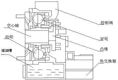
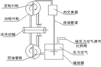
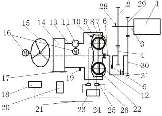
[0025] Such as image 3 The structure diagram of the independent hydraulic retarder based on magneto-rheological fluid of the present invention is shown, and the independent hydraulic retarder includes a retarder body, an electronic control system and an independent heat dissipation system. The independent retarder can be arranged at the output end of the transmission, the input end of the transmission and the input end of the rear axle as required. The present invention is only described by taking the arrangement at the output end of the transmission as an example.

[0026] The retarder body includes a moving wheel 9, a fixed wheel 8, a working chamber 22, a moving wheel shaft 6, a retarder housing 17, a coil 12, a vehicle power supply 23, an electric brush 25 and a copper ring 24, etc. The cross-sections of the moving wheel 9 and the fixed wheel 8 are both semi-circular, and the moving wheel 9 and the fixed wheel 8 are coaxial and opposite with a gap, and are located in the...


PUM


Abstract

The invention discloses an independent type automobile hydraulic retarder based on a magnetorheological fluid and a control method thereof. A working cavity is sealed, the magnetorheological fluid is filled in the working cavity, a driving wheel, a fixed wheel, a coil and a cooling water jacket are accommodated in the working cavity, the moving wheel and the fixed wheel are coaxially opposed with clearance, the coil is winded around the outer edges of the moving wheel and the fixed wheel, the coil is fixed at the outer edge of the moving wheel, a clearance exists between the coil and the outer edge of the fixed wheel, the coil is connected with a vehicle power supply outside the working cavity, an output end of a moving wheel shaft extends out of the working cavity and is connected with a speed changer through a driving gear pair, the cooling water jacket is fixedly sleeved on the fixed wheel outer ring, the cooling water jacket is connected with a water pump and a radiator outside the working cavity, according to vehicle information of a vehicle controller, an electronic control unit calculates the current which is input into the coil, establishes magnetic field in the working cavity and generates a braking torque which acts on the moving wheel shaft, the electronic control unit controls the water pump to work so that the cooling water can circularly flows among a cooling water pipeline, the cooling water jacket and the radiator, and the temperature of the magnetorheological fluid can be decreased.

Description

technical field [0001] The invention relates to automobile hydraulic retarder technology, in particular to an independent automobile hydraulic retarder using magnetorheological fluid as a working fluid and a control method thereof. Background technique [0002] At present, the mature hydraulic retarder is represented by the Voith R133-2 type, and the structure of the Voith R133-2 hydraulic retarder is as follows: figure 1 As shown, it includes a moving wheel, a fixed wheel, a working chamber, a hollow shaft, a heat exchanger, and an oil storage tank. For automatic transmission vehicles equipped with hydraulic transmissions, the original transmission system has been equipped with components such as oil storage tanks, oil pumps and radiators. Therefore, hydraulic retarders are installed on passenger cars and trucks equipped with automatic transmissions. The cost is lower. When working, it works like figure 2 , the compressed air enters the oil storage tank through the sol...

Claims


Application Information

Patent Timeline
Patent Type & Authority Applications(China)
IPC IPC(8): F16D57/02F16D65/14F16D65/78F16F9/53F16D121/02F16D129/08
Inventor 何仁胡东海
Owner JIANGSU UNIV
Why Eureka
Try Eureka