Sealing device for transmission input shafts in vacuum environment and using method of sealing device
What is Al technical title?
Al technical title is built by PatSnap Al team. It summarizes the technical point description of the patent document.
A sealing device and vacuum environment technology, which is applied in the direction of engine sealing, engine components, mechanical equipment, etc., can solve the problems of shortened service life, difficulty, and impossibility, etc., to achieve extended service life, good vacuum sealing, and improved magnetic effect of effect
Inactive Publication Date: 2013-02-13
浙大新剑(上海)智能技术有限公司 +1
View PDF8 Cites 15 Cited by
Summary
Abstract
Description
Claims
Application Information
AI Technical Summary
This helps you quickly interpret patents by identifying the three key elements:
Problems solved by technology
Method used
Benefits of technology
Problems solved by technology
The conventional solution to sealing is to use multi-stage sealing rings for sealing, but for high-required vacuum sealing, such as the vacuum degree of single crystal growth environment requiring more than 99.99%, multi-stage sealing rings are used to It is very difficult to achieve sealing, and it may be necessary to use multi-stage sealing rings to meet the vacuum requirements, but it cannot be achieved in a limited space
With the advancement of scientific research in recent years, people have widely used the effect of magnetic fields and found that ferrofluid can be used as a seal, but in specific use, it is not as simple as our commonly used O-rings. To its flow and sealing, and because of its magnetic properties, it is necessary to consider the matching magnetic poles, relative positions, etc. Different spaces and different installation positions will affect the sealing effect of magnetic fluid
And because the magnetic fluid seal often works in a hot field environment, the related parts are easily damaged by heat, which affects the magnetic effect of the magnetic work piece and shortens the service life
Method used
Image
Click on the blue label to locate the original text in one second.
Reading with bidirectional positioning of images and text.
Examples
Embodiment Construction
[0017] The present invention will be further described below in conjunction with the accompanying drawings and specific embodiments.
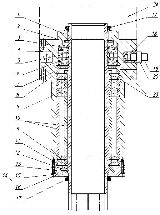
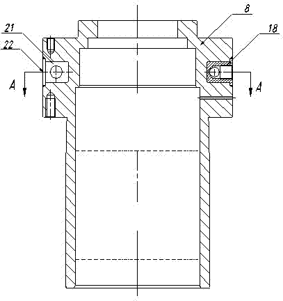
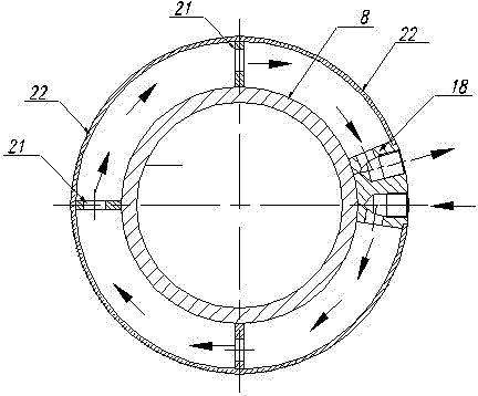
[0018] Such as Figure 1-3 As shown, the sealing device for transmission input shaft in a vacuum environment includes transmission input shaft 1, shaft circlip 2, magnetic liquid 3, magnetic pole 4, magnetic block 5, O-ring 6, special gasket 7, outer shell 8 , Angular contact ball bearing 9, matching ring 10, locking block 11, flat end screw 12, end cover 13, hexagon socket head screw 14, glue 15, lock nut 16, V-shaped oil seal 17, four-way connection Block 18, water outlet pipe joint 19, water inlet pipe joint 20, slow water block 21, water channel outer hoop piece 22, grease 23, vacuum seal cavity 24, oil seal limit groove 25, retaining ring shaft groove 26, magnetic liquid chamber 27 , shaft shoulder 28, locking thread 29 and bisected shaft slit 30; the shaft circlip 2 is mounted on the circlip shaft groove 26 of the transmission input shaf...
PUM
Abstract
The invention discloses a sealing device for transmission input shafts in a vacuum environment and a using method of the sealing device. The sealing device comprises a transmission input shaft, elastic shaft check rings, magnetic liquids, magnetic poles, magnets, O-shaped rings, special-made gaskets, outer casings, angular contact ball bearings, pairing ferrules, locking blocks, set screws with flat points, end caps, hexagon socket head cap screws, glue, lock nuts, V-shaped oil seals, a four-way connection block, a water outlet connector, a water inlet connector, a water delaying baffle block, outer water channel ferrule pieces and oil, wherein an oil seal limiting groove, check ring shaft grooves, magnetic liquid chambers, shaft shoulders, locking threads and equal division shaft kerfs are arranged on the transmission input shaft. According to the sealing device, novel magnetic fluid materials are applied for vacuum seal, a water cooling system is applied for cooling, by means of the sealing device, thermal damage is reduced in thermal field environments, magnetic effects of magnetism work pieces are improved, the vacuum sealing performance is good, and the sealing device can be used in vacuum sealing devices with higher vacuum requirements.
Description
technical field [0001] The present invention relates to the most critical vacuum sealing problem during the power input of mechanical equipment working in a vacuum environment, and also relates to the cooling problem of mechanical parts working in a thermal field environment, and especially relates to a sealing device for a transmission input shaft in a vacuum environment and how to use it. Background technique [0002] For mechanical equipment working in a vacuum-sealed environment, the required power must be provided by the outside. In the process of transmitting power to the vacuum chamber, there is a vacuum sealing problem, especially for the rotating transmission shaft, the vacuum sealing is a difficult problem. . The conventional solution to sealing is to use multi-stage sealing rings for sealing, but for high-required vacuum sealing, such as the vacuum degree of single crystal growth environment requiring more than 99.99%, multi-stage sealing rings are used to I...
Claims
Application Information
Patent Timeline
Application Date:The date an application was filed.
Publication Date:The date a patent or application was officially published.
First Publication Date:The earliest publication date of a patent with the same application number.
Issue Date:Publication date of the patent grant document.
PCT Entry Date:The Entry date of PCT National Phase.
Estimated Expiry Date:The statutory expiry date of a patent right according to the Patent Law, and it is the longest term of protection that the patent right can achieve without the termination of the patent right due to other reasons(Term extension factor has been taken into account ).
Invalid Date:Actual expiry date is based on effective date or publication date of legal transaction data of invalid patent.