Microscope objective optical system for video imaging

A technology of microscopic objective lens and optical system, which is applied in the technical field of optical instruments in Ming Dynasty

Inactive Publication Date: 2013-02-13
SHANGHAI INST OF OPTICS & FINE MECHANICS CHINESE ACAD OF SCI
View PDF4 Cites 22 Cited by
  • Summary
  • Abstract
  • Description
  • Claims
  • Application Information

AI Technical Summary

Problems solved by technology

[0005] Modern microscope objective lens has reached a high degree of perfection, its Numerical aperture is close to the limit, the center of the field of view resolution The difference from the theoretical value is very small. However, the possibility of increasing the field of view of the microscope objective lens and improving the imaging quality at the edge of the field of view still exists. This kind of research work is still in progress.

Method used


Image

  • Microscope objective optical system for video imaging
  • Microscope objective optical system for video imaging
  • Microscope objective optical system for video imaging

Examples


Embodiment Construction

[0024] The present invention will be further described below in conjunction with the accompanying drawings and embodiments, but the protection scope of the present invention should not be limited thereby.

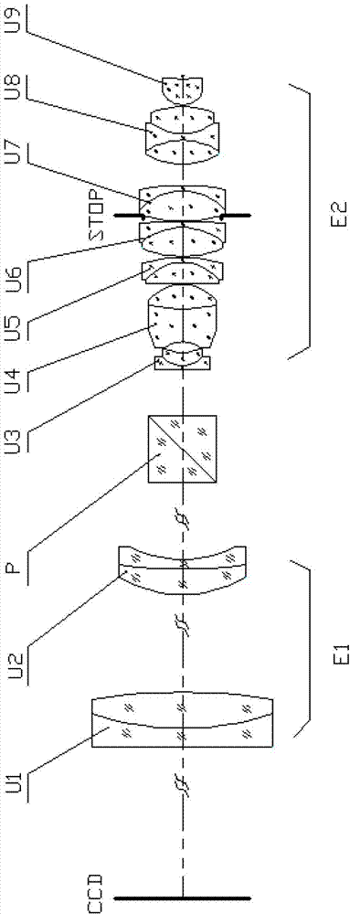
[0025] see figure 1 , the present invention is used for the microscope objective lens optical system of video display imaging, consists of the first lens group U1, the second lens group U2, the dichroic prism P, the third lens group U3, the fourth lens group U4, the fifth lens group U5, The sixth lens group U6, the seventh lens group U7, the eighth lens group U8, and the ninth lens group U9 are arranged sequentially along the optical axis from left to right, and the first lens group U1 and the second lens group U2 constitute a system The front objective lens group E1, the third lens group U3 to the ninth lens group U9 form the main objective lens group E2 of the system; its characteristics are: the focal length of the third lens group U3 is fU3, and the focal length of the...


PUM


Abstract

The invention provides a microscope objective optical system for video imaging, which is formed by sequentially arranging a first lens set, a second lens set, a light splitting prism, a third lens set, a fourth lens set, a fifth lens set, a sixth lens set, a seventh lens set, an eighth lens set and a ninth lens set along an optical axis from left to right, wherein a pre-positioned objective set of the system is formed by the first lens set and the second lens set; a main objective set of the system is formed by the third lens set, the fourth lens set, the fifth lens set, the sixth lens set, the seventh lens set, the eighth lens set and the ninth lens set; the focal length of the third lens se is fU3, the focal length of the fourth lens set is fU4 and the focal length of the main objective set is fE2; and a relation of the fU3, the fU4 and the fE2 is as follows: the absolute value of fU3 / fU4 is more than 0.46 and less than 0.68, and absolute value of fU3 / fE2 is more than 6.23 and less than 7.53. The microscope objective optical system disclosed by the invention has the characteristics of large-numerical-value hole diameter, large view field, long working distance, small relative distortion and high amplification factor in a waveband range of 360-550nm, and the imaging quality of the system reaches to the diffraction limit.

Description

technical field [0001] The invention belongs to the technical field of optical instruments, in particular to a microscopic objective optical system for video imaging, which is mainly applicable to the inspection of electronic industry production lines, the verification of printed circuit boards, and the welding defects (printing misalignment, edge collapse, etc.), single-board PC verification, vacuum fluorescent display VFD verification, and plant epidermis observation by the Academy of Forestry, skin inspection in the beauty industry, etc., it will enlarge the image of the object and display it on the microscope screen. And it can be taken into pictures or videos for further analysis and processing. Background technique [0002] With the rise of CCD cameras, microscopes can transfer real-time images to TVs or monitors for direct observation, and can also be photographed by cameras. With the development of the digital industry and the computer industry, the functions of the...

Claims


Application Information

Patent Timeline
Patent Type & Authority Applications(China)
IPC IPC(8): G02B13/00G02B13/22G02B1/00G02B21/02G02B21/36
Inventor 曹红曲步扬王向朝徐文东袁春晓徐静浩
Owner SHANGHAI INST OF OPTICS & FINE MECHANICS CHINESE ACAD OF SCI
Why Eureka
Try Eureka