Microtopological-structure plate flow chamber capable of applying electric and shearing force stimulation
A technology of flat flow cavity and topology structure, applied in the field of flat flow cavity, to achieve the effect of simple and compact structure
- Summary
- Abstract
- Description
- Claims
- Application Information
AI Technical Summary
Problems solved by technology
Method used
Image
Examples
Embodiment 1
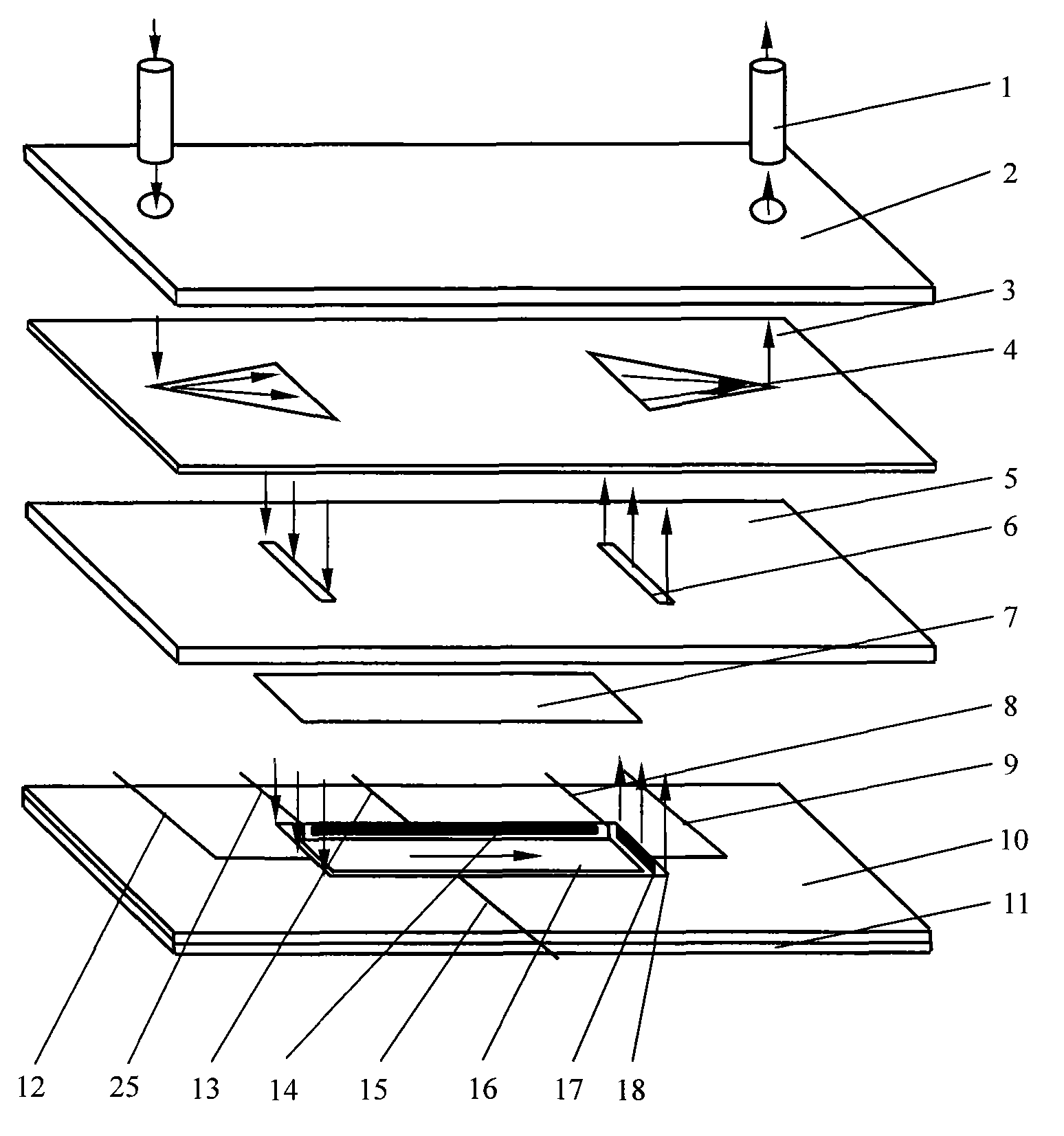
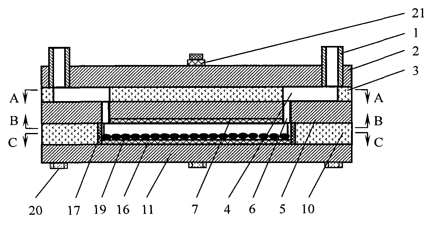
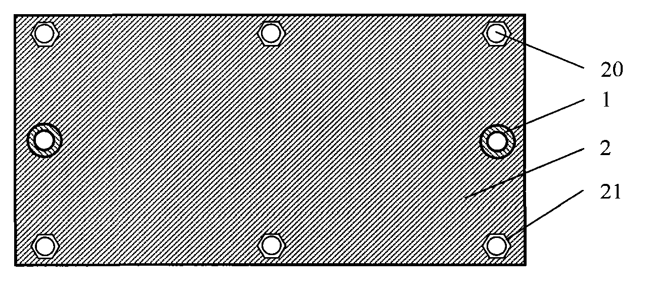
[0026] Depend on figure 1 , figure 2 , image 3 and Figure 4 It can be seen that the flat plate flow chamber that can implement multi-directional electrical stimulation of the present invention is composed of three layers of flat plates and two layers of gaskets. A rectangular slit 6 is provided, and the lower gasket 10 is provided with a flow cell 18 . Both the width and length of the flow cell 18 should be substantially greater than the difference between the thickness of the flow cell 18 and the thickness of the electrode plate 16 placed therein. The upper plate 2, the middle plate 5 and the lower plate 11 can be made of polycarbonate, Plexiglas or metal, and the upper gasket 3 and the lower gasket 10 can be made of silicone resin or the like. like Figure 5 , Image 6 and Figure 7 It can be seen that the culture solution enters the triangular diversion groove 4 in the upper gasket 3 from the upper conduit 1 of the upper plate 2, so that the fluid is fully dispers...
Embodiment 2
[0045] The micro-topology structure on the electrode plate 16 of the present invention is not limited to the micro-grooves provided in Embodiment 1, and micro-bosses of various shapes such as triangles, quadrilaterals, pentagons, hexagons or cylinders can also be formed on the silicon wafer array. Take the square boss as an example, Figure 10 is the top view of the electrode plate on the bottom of the flow cell with a flat flow cavity with microtopology that can be stimulated by electrical and shear forces, Figure 11 Yes Figure 10 Electrode plates along the bottom of a flow cell with a flat flow chamber with microtopology that can be stimulated by electrical and shear forces are shown. Figure 10 Sectional view of line E-E in . In order to obtain the electrode plate as shown in the figure, a square micro-protrusion array can be formed on the silicon wafer first. Other regular or irregular patterns of micro-boss arrays can also be formed according to this method. The ot...
Embodiment 3
[0047] The electrode plate 16 of the present invention can be prepared into a flat plate with a uniform thickness to achieve uniform fluid shearing force. The electrode plate 16 can also be prepared as a wedge-shaped plate with a uniform thickness to achieve continuous shear force action. Figure 12 is a cross-sectional view of the electrode plate 16 whose thickness varies uniformly, Figure 13 Yes Figure 12 A side view of the bottom electrode plate 16 is shown. When preparing the electrode plate 16 with uniform thickness, the thickness of the PDMS film 23 can be kept uniform, and the sheet 22 can be made into a wedge shape with an inclination of 5-60°, or the thickness of the sheet 22 can be kept uniform, and the PDMS film 23 can be made 5-60° Wedge of inclination. In order to facilitate processing, it is preferable to keep the thickness of the PDMS film 23 uniform, and the sheet 22 is made into a wedge shape with an inclination of 5-60°. Other methods and structures are...
PUM
| Property | Measurement | Unit |
|---|---|---|
| diameter | aaaaa | aaaaa |
| diameter | aaaaa | aaaaa |
Abstract
Description
Claims
Application Information
 - R&D
- Intellectual Property
- Life Sciences
- Materials
- Tech Scout
- Unparalleled Data Quality
- Higher Quality Content
- 60% Fewer Hallucinations
Browse by: Latest US Patents, China's latest patents, Technical Efficacy Thesaurus, Application Domain, Technology Topic, Popular Technical Reports.
© 2025 PatSnap. All rights reserved.Legal|Privacy policy|Modern Slavery Act Transparency Statement|Sitemap|About US| Contact US: help@patsnap.com


