
System, device and method for transmitting near-bit drilling signals

A signal transmission system and signal transmission technology, applied in the field of near-bit drilling signal transmission system, can solve the problems of low transmission rate, large path loss, high bit error rate, etc., and achieve stable transmission channel, long transmission distance and high transmission rate Effect

Inactive Publication Date: 2013-02-20
CHINA UNIV OF PETROLEUM (BEIJING)
View PDF5 Cites 15 Cited by
  • Summary
  • Abstract
  • Description
  • Claims
  • Application Information

AI Technical Summary

Problems solved by technology

[0005] The main purpose of the embodiments of the present invention is to provide a near-bit drilling signal transmission system, equipment and method to solve the problem of high implementation cost or channel instability, large path loss, low transmission rate and error in the prior art near-bit signal transmission system. The problem of high code rate

Method used


Image

  • System, device and method for transmitting near-bit drilling signals
  • System, device and method for transmitting near-bit drilling signals
  • System, device and method for transmitting near-bit drilling signals

Examples


Embodiment 1

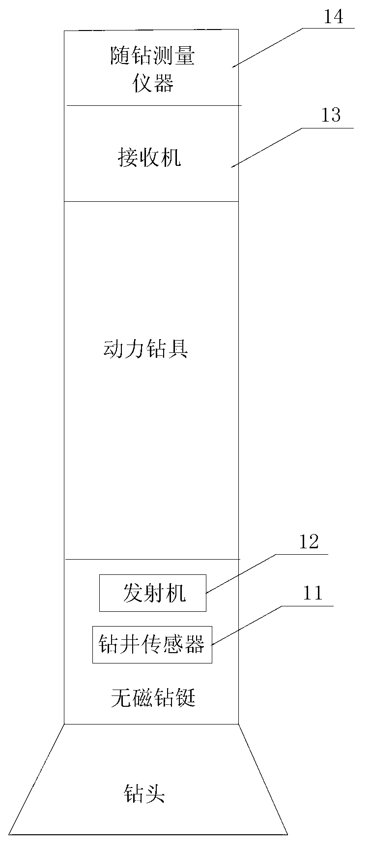
[0051] This embodiment provides a near-bit drilling signal transmission system, such as figure 1 As shown, the near-bit drilling signal transmission system includes: a drilling sensor 11, a transmitter 12, a receiver 13 and a measurement-while-drilling instrument 14; wherein,

[0052] The drilling sensor 11 is packaged inside the non-magnetic drill collar between the power drill and the drill bit, and is used to measure the drilling trajectory parameter information and send it to the transmitter 12;

[0053] The transmitter 12 is packaged inside the non-magnetic drill collar between the power drilling tool and the drill bit, connected to the drilling sensor 11, and used to generate an alternating magnetic field according to the drilling trajectory parameter information;

[0054] The receiver 13 is arranged at the end of the power drilling tool close to the measuring instrument 14 while drilling, and is used to generate an induced current signal by using the alternating magneti...

Embodiment 2

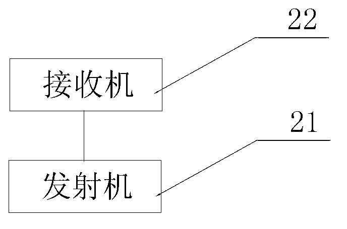
[0059] This embodiment provides a near-bit drilling signal transmission device, such as figure 2 As shown, the device includes: a transmitter 21 and a receiver 22; wherein,

[0060] The transmitter 21 is encapsulated inside the non-magnetic drill collar arranged between the power drilling tool and the drill bit, and is connected to the drilling sensor for receiving the drilling trajectory parameter information sent by the drilling sensor, and generating alternating magnetic field;

[0061] The receiver 22 is arranged at the end of the power drilling tool close to the measurement-while-drilling instrument, and is used to generate an induced current signal by using the alternating magnetic field, acquire the drilling trajectory parameter information according to the induced current signal, and transfer the acquired The drilling trajectory parameter information is sent to the measurement-while-drilling instrument.

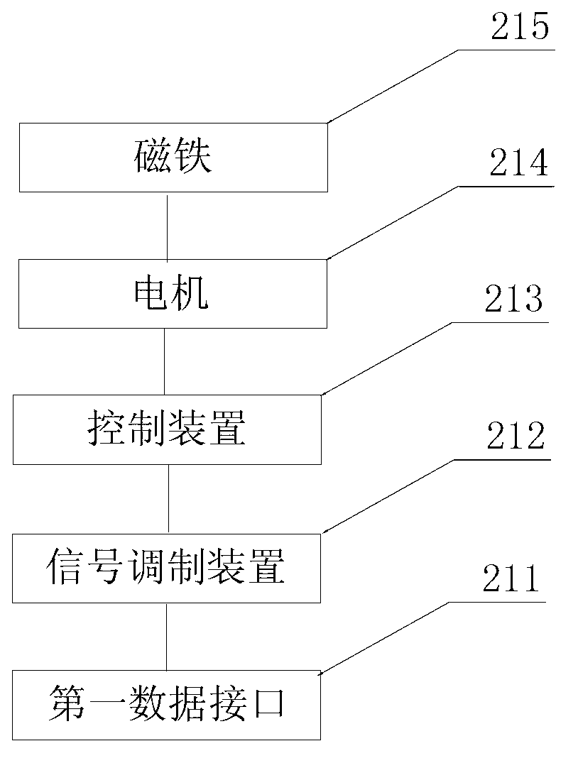
[0062] Specifically, in this embodiment, the transmitter 21 i...

Embodiment 3

[0083] This embodiment provides a near-bit drilling signal transmission method, such as Figure 6 As shown, the method includes:

[0084] Step S61, the transmitter receives the drilling trajectory parameter information sent by the drilling sensor, and generates an alternating magnetic field according to the drilling trajectory parameter information, and the transmitter is packaged inside the non-magnetic drill collar between the power drilling tool and the drill bit;

[0085] Step S62, the receiver uses the alternating magnetic field to generate an induced current signal, obtains the drilling trajectory parameter information according to the induced current signal and sends it to the measurement-while-drilling instrument, and the receiver is arranged on a power drilling tool close to the measurement-while-drilling instrument Ends.

[0086] This embodiment is based on the principle of electromagnetic induction. The transmitter close to the drill bit generates an alternating ma...


PUM


Abstract

The invention provides a system, a device and a method for transmitting near-bit drilling signals. The system comprises a drilling sensor, a sender, a receiver and a measuring instrument while drilling, wherein the drilling sensor is packaged in a non-magnetic drill collar arranged between a power drilling tool and a drill and used for measuring drilling track parameter information and sending the information to the sender; the sender is packaged in the non-magnetic drill collar arranged between the power drilling tool and the drill, connected with the drilling sensor, and used for generating an alternating magnetic field according to the drilling track parameter information; the receiver is arranged at the end of the power drilling tool close to the measuring instrument while drilling, used for generating induced current signals by using the alternating magnetic field, and obtaining the drilling track parameter information according to the induced current signals and sending the information to the measuring instrument while drilling; and the measuring instrument while drilling is arranged between the power drilling tool and the ground and used for sending the drilling track parameter information to a ground receiver. According to the system, the device and the method, the drilling track parameter information collected by the drilling sensor is sent to the measuring instrument while drilling in the transmission mode in which the transmission channel is stable, the transmission rate is high and the bit error ratio is low.

Description

technical field [0001] The invention relates to the technical fields of oil, natural gas and coalbed methane exploitation, and in particular relates to a near-drill drilling signal transmission system, equipment and method. Background technique [0002] In the directional drilling construction of oil, natural gas and coalbed methane, etc., obtaining the drilling trajectory parameters is crucial to the success of the construction. As the geological environment faced by the drilling industry is becoming more and more complex, the control accuracy requirements of the drilling trajectory are also increasing. . [0003] During the drilling process, the drilling trajectory parameters are mainly reflected in the inclination angle, azimuth angle and other data of the wellbore where the drill bit is located. At present, the measurement while drilling (MWD) is generally used to measure the drilling trajectory parameters. However, due to the Construction requires the use of power dril...

Claims


Application Information

Patent Timeline
Patent Type & Authority Applications(China)
IPC IPC(8): E21B47/13G08C17/02
Inventor 双凯牛迪李伟根
Owner CHINA UNIV OF PETROLEUM (BEIJING)
Learn More