Direct-current converter station based on bipolar structure

A DC converter station, bipolar technology, applied in the field of DC converter stations, can solve the problems of limited transmission capacity of converter transformers, large steady-state operation losses, and difficulty in selecting reactance parameters, so as to improve system reliability and improve Flexible and diverse effects in engineering design and operation

Inactive Publication Date: 2013-02-20
ZHEJIANG UNIV
View PDF2 Cites 47 Cited by
  • Summary
  • Abstract
  • Description
  • Claims
  • Application Information

AI Technical Summary

Problems solved by technology

[0004] First, the design and installation of the grounding method are difficult
There are mainly two existing technologies. One is to install a three-phase star-connected reactance branch on the MMC valve side to provide a reference potential for the converter station. The DC transmission system using this technology is as follows: figure 1 As shown in (a), it is difficult to select the reactance parameters of this technology, and it greatly affects the operating range of the reactive power of the converter itself
The other is the large resistance clamp grounding method on the DC side. The DC transmission system using this grounding method is as follows: figure 1 As shown in (b), but this grounding method is closely related to the selection of resistance parameters. When the resistance is too small, the steady-state operation loss will be large. When the resistance is too large, the entire system will not be grounded, and the requirements for system insulation coordination are high.
[0005] Second, the reliability of the system operation is low
None of the existing technologies clearly pointed out that smoothing reactors should be installed on the DC side, so it is necessary to increase the parameters of the bridge arm reactors to suppress the rising rate of the fault current on the DC side; and it can only operate in bipolar operation composed of a single voltage source converter. mode, once the DC line fails, it is very prone to bipolar outage, that is, the entire system is out of service, and the system reliability is low
[0006] Third, the delivery ca

Method used


Image

  • Direct-current converter station based on bipolar structure
  • Direct-current converter station based on bipolar structure
  • Direct-current converter station based on bipolar structure

Examples


Embodiment Construction

[0040] In order to describe the present invention more specifically, the technical solutions and related principles of the present invention will be described in detail below in conjunction with the accompanying drawings and specific embodiments.

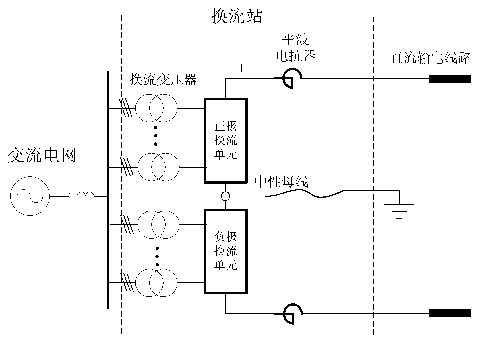
[0041] Such as figure 2 As shown, a DC converter station based on bipolar structure includes: a converter, multiple converter transformers and two smoothing reactors.

[0042] The converter consists of two converter units; one end of the positive converter unit is the positive terminal of the converter, the other end of the positive converter unit is connected to one end of the negative converter unit and grounded through the neutral bus, and the negative The other end of the converter unit is the negative terminal of the converter. The positive and negative terminals of the converter station are respectively connected to the DC transmission line through two smoothing reactors.

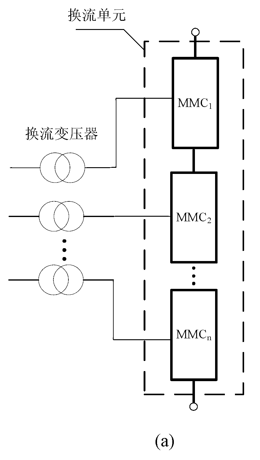
[0043] The converter unit can be composed of n MMCs ...


PUM


Abstract

The invention discloses a direct-current converter station based on a bipolar structure. The direct-current converter station consists of two convertor units connected in series, the serial connection point of the two convertor units is grounded by a neutral bus, and each convertor unit consists of a plurality of MMC (Modular Multilevel Converter) which are connected in series and in parallel. With the structure, when direct current fails, only the fault pole is affected, and a perfect pole is hardly affected, so the system reliability is improved; meanwhile, according to the direct-current converter station, the neutral bus is led out to be grounded, the stage construction and capacity-increasing construction of a system can be conducted easily, and a single pole is firstly put into operation, then double poles are put into operation, so that investment benefits can be obtained early; and simultaneously, the neutral bus is grounded by a grounding pole guide line to provide a current backflow access to a system in a single-pole ground loop operation mode, and when the system is in balance operation, the grounding current is extremely low.

Description

technical field [0001] The invention belongs to the technical field of electric power system commutation, and in particular relates to a DC converter station based on a bipolar structure. Background technique [0002] Modular Multilevel Converter (MMC) adopts the form of sub-module cascading, which has low requirements for consistent triggering of devices and dynamic voltage equalization, good scalability, high-quality output voltage waveform, low switching frequency, and low operating loss. Low and many other advantages, it is the leader of the new generation of voltage source converter topology. The MMC-based high-voltage direct current transmission system (MMC-HVDC) is better than the traditional thyristor-based direct current in the grid connection of new energy sources such as photovoltaics, wind power and tidal currents, ultra-large-scale urban power transmission and distribution, remote islands, isolated loads and passive network power transmission. The power transmi...

Claims


Application Information

Patent Timeline
IPC IPC(8): H02J1/06
Inventor 徐政薛英林唐庚刘昇张哲任
Owner ZHEJIANG UNIV
Why Eureka
Try Eureka