
Voltage-adjustable piezoelectric power generation device

A piezoelectric power generation and voltage technology, applied in generator/motor, piezoelectric effect/electrostrictive or magnetostrictive motor, electrical components, etc., can solve the problems of reducing service life, energy loss, high-speed rotation, etc. Achieving the effect of wide adaptability and increased range of variation

Active Publication Date: 2013-02-27
NANJING UNIV OF AERONAUTICS & ASTRONAUTICS
View PDF4 Cites 14 Cited by
  • Summary
  • Abstract
  • Description
  • Claims
  • Application Information

AI Technical Summary

Problems solved by technology

This solution has two disadvantages: one is that the piezoelectric bimorph collides with the cam and rubs against it every time it rotates, thus causing wear and tear, resulting in energy loss and reducing the service life
The main disadvantage of this solution is that when the vehicle passes by continuously and strong wind is generated, the sign will rotate at high speed, so that the steel ball will move close to the piezoelectric conversion element, and the piezoelectric element will not receive alternating pressure. can't generate electricity

Method used


Image

  • Voltage-adjustable piezoelectric power generation device
  • Voltage-adjustable piezoelectric power generation device

Examples


Embodiment Construction

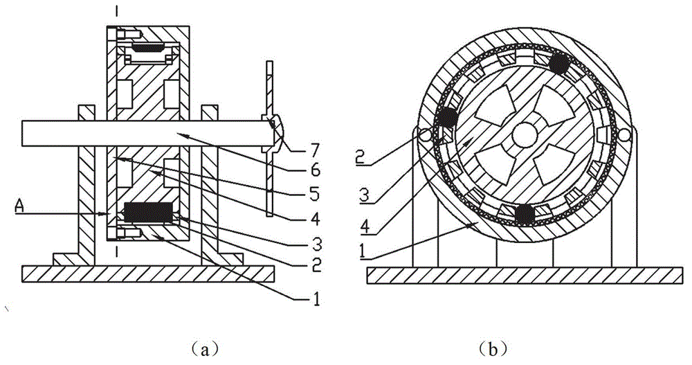
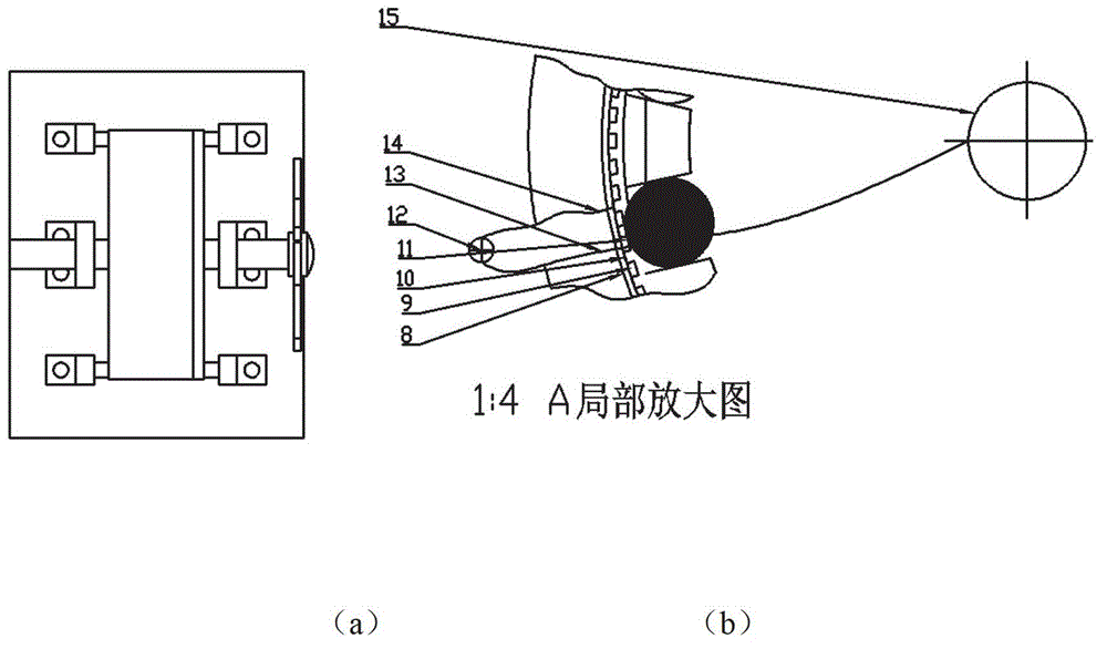
[0010] combine figure 1 ( figure 1 a. figure 1 b) and figure 2 ( figure 2 a. figure 2 b) The voltage-adjustable piezoelectric power generation device of the present invention is composed of a turbine rotor assembly, a piezoelectric coil assembly, and a roller assembly. The turbine rotor assembly includes turbine blades 7 and a rotating shaft 6, and the turbine blades 7 are fixed on the rotating shaft One end of 6 is rotated by the turbine blade 7 to drive the rotating shaft 6 to rotate;

[0011] The roller assembly consists of a rotating disc 4, a roller 2 and a cage 3. The roller 2 is limited by the rotating disc 4 and the cage 3. The roller 2 itself rotates by itself. The rotating disc 4 is fixed in the middle of the rotating shaft 6 and The rotating disk 4 and the cage 3 are clearance fit, so that the cage 3 forms a floating state, and when the rotating shaft 6 rotates, the rotating disk 4, the roller 2 and the cage 3 rotate together around the axis of the rotating ...


PUM


Abstract

The invention discloses a piezoelectric power generation device which is formed by a turbine rotor assembly, a piezoelectric ring assembly and a pin roller assembly. The turbine rotor assembly comprises turbine blades and a rotary shaft, wherein the turbine blades rotate to drive the rotary shaft to rotate and are fixed at one end of the rotary shaft. A flexible piezoelectric ring serves as a bearing type outer ring and can deform under the extrusion of a pin roller. When the number of piezoelectric unit is increased continuously, output voltage fluctuation can be decreased, accordingly, stable standard direction current output can be achieved without rectification and filtering, and the problem that the device utilizing centrifugal force to provide impact loses efficacy due to generating overlarge centrifugal force under the effect of high-speed fluid to be tightly attached onto a piezoelectric vibrator is solved.

Description

technical field [0001] The invention belongs to the fields of wind power generation and hydropower generation, in particular to a piezoelectric power generation device. Background technique [0002] Using natural wind energy and water energy to generate electricity, the self-powered system for various outdoor facilities is in line with today's energy-saving, environmental protection, and low-carbon development trends. It is used in industrial monitoring, intelligent transportation, smart grid, mine safety, environmental monitoring, safe home, Healthcare and other fields have broad application prospects. [0003] US11 / 252903, a small wind-driven generator, was designed and manufactured by Priya of the United States using piezoelectric devices. It can generate electricity under the wind power of 8-16 kilometers per hour. The generator's paddles are attached to a cam that oscillates a series of bimorphs arranged in a circle around an axis to output electricity. This solution...

Claims


Application Information

Patent Timeline
Patent Type & Authority Applications(China)
IPC IPC(8): H02N2/18
Inventor 杨颖金家楣沈钦龙
Owner NANJING UNIV OF AERONAUTICS & ASTRONAUTICS
Learn More