Air inlet duct for a turbojet nacelle

A technology of engine nacelle and turbojet, which is applied in the aviation field, can solve the problems of increasing materials and achieve the effect of preventing insufficient aerodynamic force and improving aerodynamic characteristics

Inactive Publication Date: 2013-02-27
SN DETUDE & DE CONSTR DE MOTEURS DAVIATION S N E C M A
View PDF6 Cites 8 Cited by
  • Summary
  • Abstract
  • Description
  • Claims
  • Application Information

AI Technical Summary

Problems solved by technology

[0011] However, in this case, since the composite material is not as rigid as the metal, the thickness of the material must be increased to achieve the same degree of rigidity and energy absorption, and as a result, the lip will weigh more than the metal

Method used


Image

  • Air inlet duct for a turbojet nacelle
  • Air inlet duct for a turbojet nacelle
  • Air inlet duct for a turbojet nacelle

Examples


Embodiment Construction

[0035] For a better understanding of the figures, the same reference numerals are used to designate the same technical parts.

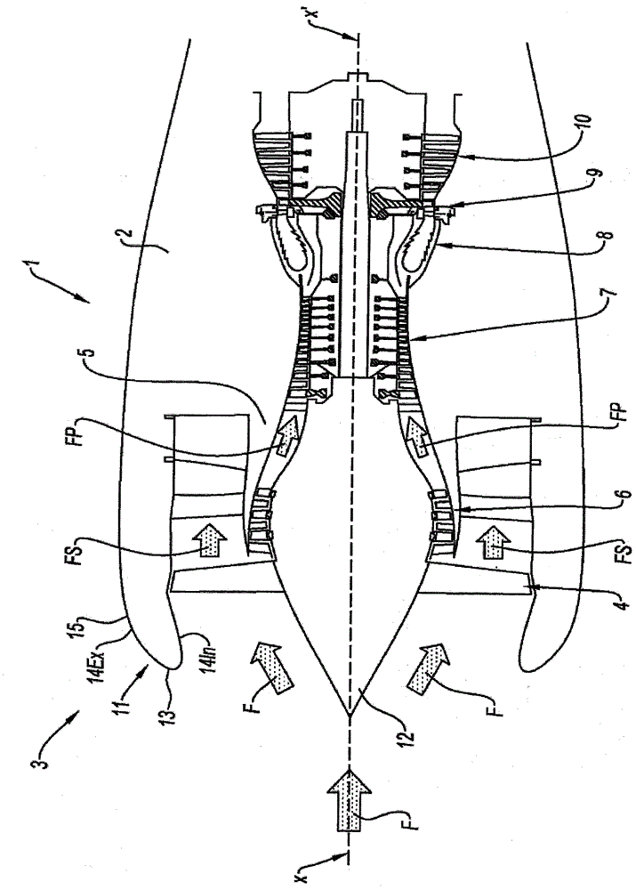
[0036] figure 1 The turbojet engine 1 in is a two-flow path and two-body engine, which is axisymmetric around the axis X-X'. In a known manner, within the nacelle 2 that is the housing of its different devices, this turbojet 1 comprises an air intake 3 through which the inflow air F can enter in order to then flow through an intake fan 4 . This air flow F is then divided into two flow paths, the primary flow path FP and the secondary flow path FS, via the intermediate casing 5, the end of which constitutes the separator nozzle.

[0037] In the following description, the terms "upstream" and "downstream" both refer to an axial position along the longitudinal axis X-X' in the direction of air flow inside the turbojet engine 1 .

[0038] The secondary flow path FS flows through the rectification stage and is discharged downstream of the turbojet. The ...


PUM


Abstract

The invention relates to an air inlet duct (11) for a turbojet nacelle, comprising an upstream annular lip (13) and a downstream outer annular structure (14Ex). The invention is characterised in that the upstream annular lip (13) and the downstream outer annular structure (14Ex) are formed as a one-piece part (15) made from composite material and in that the upstream lip (13) is covered with a metal layer (16) formed, in particular, by electrodeposition or plastic forming. The invention also relates to a turbofan engine having an air inlet duct (11) thus formed, and to a method for producing one such air inlet duct (11).

Description

technical field [0001] The invention relates to the field of aviation, in particular to a turbojet engine nacelle air inlet. Background technique [0002] The nacelles equipped on turbojet engines are generally assembled from approximately annular parts centered on an axis near the axis of the turbojet engine. From upstream to downstream, the nacelle successively includes the air intake, the fan cowl surrounding the turbojet fan, and the rear part forming the nozzle. [0003] The air intake of the nacelle makes it possible to supply the turbojet engine with a large amount of air sufficient to ensure the operation of the engine in flight conditions. To this end, the air intake generally consists of: [0004] - the upstream annular lip, which is aerodynamically shaped to provide sufficient air to the fan and the individual compressor stages; and [0005] - Downstream annular structure consisting of an inner channeling incoming air to the fan blades and an outer part facilit...

Claims


Application Information

Patent Timeline
Patent Type & Authority Applications(China)
IPC IPC(8): B64D29/00B64D33/02
CPCB64D2033/0286B64D33/02B64D29/00B64D2033/0233
Inventor 沃特·鲍克皮埃尔-阿兰·吉恩-玛丽·飞利浦·休斯·休亚德波尼特·马克·米歇尔·飞维莱特
Owner SN DETUDE & DE CONSTR DE MOTEURS DAVIATION S N E C M A
Why Eureka
Try Eureka