
Chemical-mechanical grinding device and method

A technology of chemical machinery and grinding equipment, which is applied in the direction of grinding equipment, grinding machine tools, electrical components, etc., can solve the problems of low utilization rate of grinding fluid, increase of process cost, waste of grinding fluid, etc., to reduce process cost, improve utilization rate, The effect of consumption reduction

Active Publication Date: 2013-03-06
SEMICON MFG INT (SHANGHAI) CORP
View PDF5 Cites 5 Cited by
  • Summary
  • Abstract
  • Description
  • Claims
  • Application Information

AI Technical Summary

Problems solved by technology

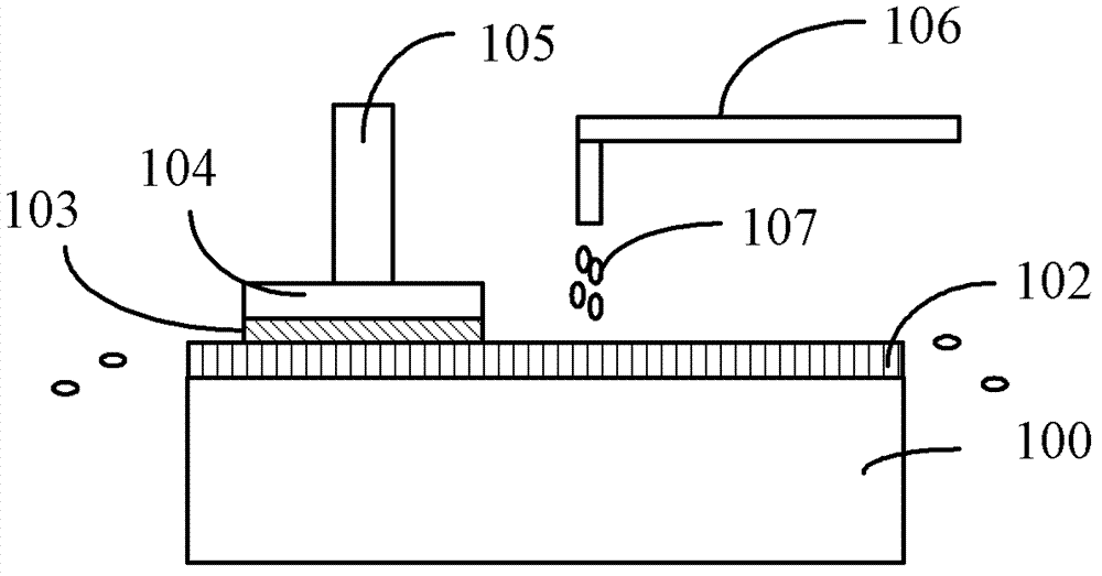
When grinding, the wafer 103 to be ground is attached to the grinding head 104, and the surface to be ground of the wafer 103 to be ground is facing downward, and is tightly attached to the ground under the downward force provided by the grinding head 104. On the grinding pad 102, when the grinding disc 100 rotates under the drive of the motor, the grinding head 104 also rotates in the same direction driven by the chuck 105, and at the same time, the grinding liquid 107 passes through the grinding liquid supply pipe 106 Transported to the grinding pad 102, under the joint action of the grinding head 104, the grinding pad 102, and the grinding disc 100, the grinding liquid is evenly distributed on the grinding pad 102, and in the grinding process, the grinding liquid is Under the effect, directly flow out from the edge of described grinding pad 102, then discharge through waste liquid pipeline, can not be used again, so just cause the great waste of grinding liquid, the utilization rate of grinding liquid is low, increased process cost

Method used


Image

  • Chemical-mechanical grinding device and method
  • Chemical-mechanical grinding device and method
  • Chemical-mechanical grinding device and method

Examples


Embodiment Construction

[0031] The inventor found that when using the existing chemical mechanical grinding device for grinding, the grinding liquid flowing out from the edge of the grinding pad also contains a large amount of unused grinding liquid stock solution. If the grinding liquid is directly discharged from the waste liquid pipeline, it will cause The great waste of grinding fluid and the low utilization rate of grinding fluid increase the process cost.

[0032] In order to solve the above problems, the inventor proposes a chemical mechanical polishing device.

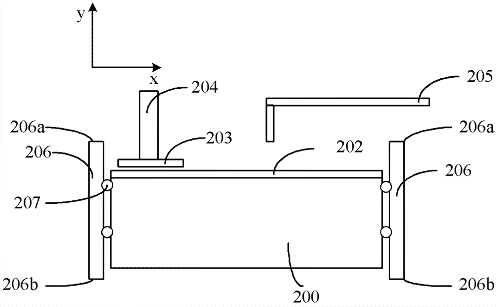
[0033] Please refer to figure 2 , is a schematic structural diagram of the chemical mechanical polishing device of the present invention.

[0034] The chemical mechanical polishing device comprises:

[0035] Grinding disc 200, described grinding disc 200 is for placing grinding pad;

[0036] Polishing pad (Polish Pad) 202, described polishing pad lays on described grinding disk 200, is used for grinding the surface to be ground of...


PUM

PropertyMeasurementUnit
Thicknessaaaaaaaaaa
Heightaaaaaaaaaa

Abstract

The invention provides a chemical-mechanical grinding device. The chemical-mechanical grinding device comprises a grinding plate, a grinding pad, a grinding head and a control ring, wherein the grinding plate is positioned on the grinding pad and is used for grinding the surface to be grinded of a wafer; the grinding head is used for clamping the wafer during grinding; the control ring, which is adjustable in height, is positioned on the outer side of the grinding plate and arranged around the grinding plate; and the control ring can be used for remaining a certain volume of grinding liquid in a position, in the control ring and above the grinding pad. By adopting the chemical-mechanical grinding device for grinding, the utilization rate of the grinding liquid in chemical-mechanical grinding can be improved, and the process cost can be reduced.

Description

technical field [0001] The invention relates to the field of semiconductor manufacturing, in particular to a chemical mechanical polishing device and a chemical mechanical polishing method. Background technique [0002] With the rapid development of Ultra Large Scale Integration (ULSI), the manufacturing process of integrated circuits has become more and more complex and sophisticated. In order to improve integration and reduce manufacturing costs, the number of components per unit area of ​​the chip is increasing, and planar wiring has been difficult to meet the requirements of high-density distribution of components. Multilayer wiring technology can only be used to utilize the vertical space of the chip to further improve the integration of devices. Spend. However, the application of multi-layer wiring technology will cause the surface of the silicon wafer to be uneven, which is extremely unfavorable for graphics production. For this reason, in order to realize a multila...

Claims


Application Information

Patent Timeline
IPC IPC(8): B24B37/02H01L21/304
Inventor 陈枫
Owner SEMICON MFG INT (SHANGHAI) CORP
Learn More