Compressor with compression pump body support member

A technology for compressing pumps and supports, which is applied to pump components, liquid fuel engines, and parts of pumping devices for elastic fluids. Performance and stability, reduction of welding deformation, effect of reducing welding strength

Active Publication Date: 2015-05-27
GREE ELECTRIC APPLIANCES INC +1
View PDF6 Cites 0 Cited by
  • Summary
  • Abstract
  • Description
  • Claims
  • Application Information

AI Technical Summary

Problems solved by technology

[0003] When the existing compressor is spot welded, the suction pipe (i.e. the intake elbow 101) of the compression pump body is inserted into the compression pump body for positioning. Since the suction port of the closed casing 100 is stamped, The trachea pipe 101 is slightly smaller than the connecting pipe at the suction port. In addition, the suction pipe is mostly made of soft and easily deformed copper pipes, which is prone to inaccurate positioning, resulting in the height difference between the stator and the rotor cannot be well guaranteed, and , before the spot welding of the compressor is completed, it is easy to make the pump body assembly and the rotor tilt to the other side of the rotor contact gap together by only relying on the suction pipe on one side of the compressor, thereby affecting the same position of the stator and rotor of the compressor. In addition, the spot welding strength of existing compressors is high and generates a lot of heat, which will lead to large deformation of the upper flange (or cylinder), and will also cause wear and stuck of the pump body parts. The performance and stability of the machine are very unfavorable

Method used


Image

  • Compressor with compression pump body support member
  • Compressor with compression pump body support member
  • Compressor with compression pump body support member

Examples


Embodiment 1

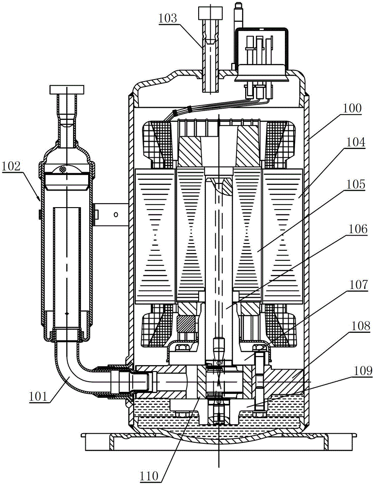
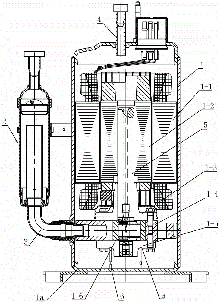
[0028] Such as figure 2 As shown, the compressor of this embodiment includes a closed casing 1, a motor assembly and a compression pump body arranged inside the closed casing 1, a gas-liquid separator 2 arranged on one side of the closed casing 1, and a gas-liquid separator 2 The intake elbow 3 communicates with the compression pump body of the compressor, so that the refrigerant enters the cylinder of the compressor from the gas-liquid separator 2 . The exhaust pipe 4 is arranged on the upper end of the closed casing 1, and the compressed high-temperature and high-pressure gas enters the circulation system from the exhaust pipe 4 . For ease of description, the figure 2 The axis direction of the middle compressor rotating shaft 5 defines up and down.

[0029] The motor assembly of the present invention includes a stator 1-1 fixed on the upper inner wall of the closed casing 1, and a rotor 1-2 rotatably arranged in the stator 1-1, and the compressor shaft 5 is driven to rot...

Embodiment 2

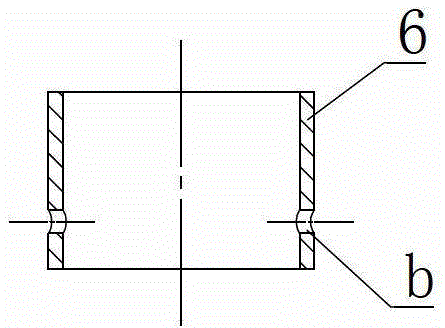
[0033] Also refer to Figure 5 , Image 6 and Figure 7 , the compression pump body support 6' of this embodiment is integrated with the lower flange 1-5, that is, the compression pump body support 6' is a part of the lower flange 1-5, and the compression pump body support 6' is located at The end of the boss part of the lower flange 1-5, the bottom of the compression pump body support 6' (that is, the bottom of the boss part of the lower flange 1-5) is directly in contact with the lower cover 1a to support the compression pump body . Four oil passage holes b arranged at intervals along the circumference are also processed on the lower peripheral wall of the compression pump body support member 6', through which refrigerated oil can enter the compression pump body, thereby lubricating the parts in the compression pump body. In this embodiment, the support member 6' of the compression pump body is made integrally with the lower flange 1-5, and the lower flange 1-5 is used fo...

Embodiment 3

[0035] Such as Figure 8 As shown, the difference between this embodiment and Embodiment 2 is that: an annular deposition groove c is processed on the upper surface of the lower cover 1a, and the deposition groove c is recessed downward from the upper surface of the lower cover 1a, so that the freezing oil The sunken impurities may be deposited in the deposition groove c. Setting the sedimentation groove c on the upper surface of the lower cover 1a does not increase the height of the compression pump body support (that is, the height of the closed casing), nor does it affect its function of isolating impurities. The number of annular deposition grooves c can be set according to needs. In this embodiment, two rings of annular deposition grooves c located on the outside of the compression pump body support 6' are provided. In addition, the deposition groove c can also be a plurality of spaced apart and form annular arc grooves or circular grooves or other grooves of different s...


PUM


Abstract

The invention relates to a compressor with a compression pump body support member. The compressor comprises a closed shell which is internally provided with a motor assembly and a compression pump body, and a gas-liquid separator communicated with the compression pump body through an air inlet elbow, wherein the compression pump body comprises an upper flange, an air cylinder and a lower flange which are axially arranged along a rotor shaft of a compressor; and the compression pump body support member is arranged between the lower flange and the lower cover of the closed shell and is used for supporting the compression pump body, the upper end of the compression pump body support member is contacted with the lower flange, and the lower end of the compression pump body support member is arranged on a lower cover. The compressor provided by the invention adopts the compression pump body support member to support the compression pump, and the length accuracy of the support member is higher than the positioning accuracy of a stamping hole in a copper suction pipe and a shell; the original unilateral locating support with a suction pipe is changed into symmetrical positioning fixation, the problem of inclination in welding is overcome, and the coaxiality of a stator and a rotor are effectively improved; and the altitude difference of the stator and the rotor is guaranteed, and the property and stability of a compressor are improved.

Description

technical field [0001] The invention belongs to the technical field of compressors, and in particular relates to a compressor provided with a support member capable of supporting a compression pump body in the compressor. Background technique [0002] Such as figure 1 As shown, it is a structural schematic diagram of a compressor in the prior art, which includes a closed casing 100 with a motor assembly and a compression pump body inside, and communicates with the compression pump body in the compressor through an intake elbow 101 The gas-liquid separator 102 is provided with an exhaust pipe 103 at the upper end of the closed casing 100 . The motor assembly of the compressor includes a stator 104 and a rotor 105 rotatably disposed in the stator 104 , and the compressor shaft 106 is driven to rotate by the rotor 105 . The compression pump body includes an upper flange 107, a cylinder 108 and a lower flange 109 installed in sequence along the axial direction of the compresso...

Claims


Application Information

Patent Timeline
Patent Type & Authority Patents(China)
IPC IPC(8): F04C29/00
Inventor 刘达炜
Owner GREE ELECTRIC APPLIANCES INC
Why Eureka
Try Eureka