Common optical path interference detecting device based on synchronous carrier phase shift and a detecting method of common optical path interference detecting device

A technology of interference detection and common optical path, applied in the field of optics, can solve the problems of low light utilization, complex data processing, etc., and achieve the effect of convenient and flexible operation, high light utilization, and simple mapping relationship

Inactive Publication Date: 2013-03-06
HARBIN ENG UNIV
View PDF2 Cites 22 Cited by
  • Summary
  • Abstract
  • Description
  • Claims
  • Application Information

AI Technical Summary

Problems solved by technology

This method eliminates the zero-frequency component by subtracting two phase-shifted interference patterns, thereby reducing the requirements for the carrier frequency in the interference pattern and improving the utilization

Method used


Image

  • Common optical path interference detecting device based on synchronous carrier phase shift and a detecting method of common optical path interference detecting device
  • Common optical path interference detecting device based on synchronous carrier phase shift and a detecting method of common optical path interference detecting device
  • Common optical path interference detecting device based on synchronous carrier phase shift and a detecting method of common optical path interference detecting device

Examples


specific Embodiment approach 1

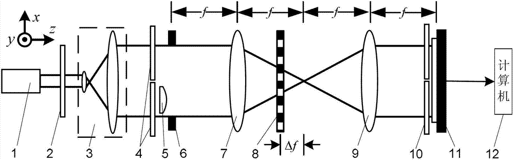
[0038] Specific implementation mode one: the following combination figure 1 This embodiment is described. The common optical path interference detection device based on synchronous carrier frequency phase shifting described in this embodiment includes a light source 1, a polarizer 2, a collimating beam expander system 3, two λ / 4 wave plates 4, and a Object 5, rectangular window 6, first lens 7, one-dimensional periodic grating 8, second lens 9, polarizer group 10, image sensor 11 and computer 12, where λ is the light wavelength of light beam emitted by light source 1,

[0039] The beam emitted by the light source 1 is incident on the light receiving surface of the collimated beam expander system 3 through the polarizer 2, and the outgoing beam after being collimated and expanded by the collimated beam expander system 3 passes through two λ / 4 wave plates 4, to be tested The object 5 and the rectangular window 6 are then incident on the first lens 7, and the outgoing light beam ...

specific Embodiment approach 2

[0048] Embodiment 2: In this embodiment, Embodiment 1 is further described. The one-dimensional periodic grating 8 is a binary one-dimensional periodic grating, a sine one-dimensional periodic grating or a cosine one-dimensional periodic grating.

[0049] In this embodiment, the one-dimensional periodic amplitude grating 8 adopts a Ronchi grating with a period d=50 μm.

specific Embodiment approach 3

[0050] Specific embodiment three: this embodiment will further illustrate embodiment one or two, the polarizer group 10 is made up of two polarizers, and the two polarizers form a 1×2 array, and the light transmission axes of the two polarizers are in line with the The x-axis is at 0° and 45°, respectively.


PUM

PropertyMeasurementUnit
Wavelengthaaaaaaaaaa

Abstract

The invention relates to a common optical path interference detecting device based on synchronous carrier phase shift and a detecting method of the common optical path interference detecting device, which belong to the optical field and solve defects in the prior art. The common optical path interference detecting device comprises an optical source, a polarizing film, a collimation and beam expansion system, two lambda/4 wave plates, an object to be detected, a rectangular window, a first lens, a one-dimensional period optical grating, a second lens, a polarizing film set, an image sensor and a computer. The detecting method comprises the steps that the light source is turned on, light beams emitted by the light source are subjected to collimation and beam expansion through the polarizing film and the collimation and beam expansion system to form parallel polarized light beams, the parallel polarized light beams sequentially pass through the first lens, the one-dimensional period optical grating and the second lens to generate diffraction light beams of 0 level and +/-1 level after passing through the two lambda/4 wave plates, the object to be detected and the rectangular window, the diffraction light beams generate interference on the surface of the image sensor after being filtered through the polarizing film set, two interference image samples are obtained by splitting interference images acquired by the computer according to the sizes of small windows of the rectangular window, and the phase distribution of the object to be detected is obtained through computation.

Description

technical field [0001] The invention relates to a common optical path interference detection device and method based on synchronous carrier frequency phase shifting, and belongs to the field of optics. Background technique [0002] Carrier frequency interferometry uses object light and reference light with a certain angle to interfere, and the phase information of the object to be measured can be obtained from the formed single carrier frequency interferogram, which is suitable for real-time measurement of moving objects or dynamic processes. Method In order to reproduce the complex amplitude distribution of object light from a single interference pattern, it is necessary to tilt the object light and reference light to obtain a large enough angle to separate the zero-frequency component, real image and conjugate image of the interference pattern on the spectrum plane, and then The lateral resolution or spatial bandwidth product of the image sensor cannot be fully utilized. ...

Claims


Application Information

Patent Timeline
IPC IPC(8): G01J9/02
Inventor 钟志单明广郝本功张雅彬窦峥刁鸣
Owner HARBIN ENG UNIV
Why Eureka
Try Eureka