Ray representation method of gyrotron quasi-optical output system

A technology of light output and representation, applied in the microwave field, can solve the problems of huge computing resources and computers, difficult to design work of quasi-optical mode converters, etc., and achieve the effect of low cost

Active Publication Date: 2013-03-06
INST OF ELECTRONICS CHINESE ACAD OF SCI
View PDF4 Cites 9 Cited by
  • Summary
  • Abstract
  • Description
  • Claims
  • Application Information

AI Technical Summary

Problems solved by technology

For millimeter waves or submillimeter waves, the quasi-optical mode converter is electrically large in both horizontal and vertical dimensions. When high-frequency simulation software is used to perform full three-dimensional high-frequency simulation calculations on the quasi-optical mode converter It is difficult to effectively and quickly guide the design of quasi-optical mode converters when huge computing resources and computers are required

Method used


Image

  • Ray representation method of gyrotron quasi-optical output system
  • Ray representation method of gyrotron quasi-optical output system
  • Ray representation method of gyrotron quasi-optical output system

Examples


Embodiment Construction

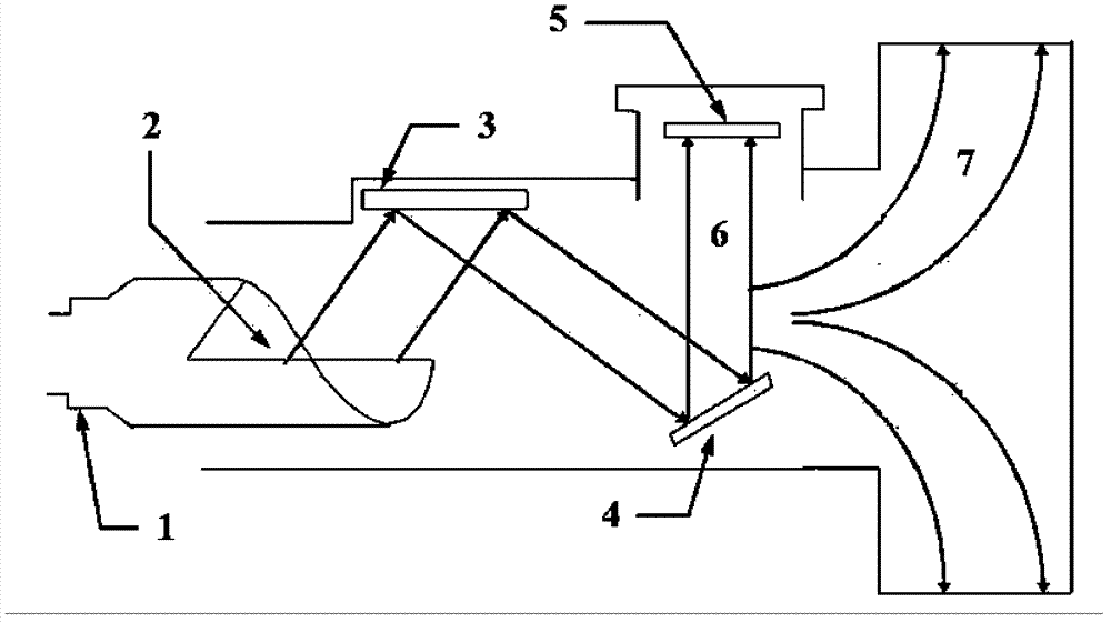
[0033] A ray representation method of a gyrotron quasi-light output system of the present invention is based on the ray-like characteristics of millimeter waves or submillimeter waves, the millimeter wave beam generated from the gyrotron radiator is equivalent to an optical ray, and the millimeter wave beam is first The propagation characteristics on the first specular reflector and the second specular reflector are equivalent to the ray propagation process of light rays on the first specular reflector and the second specular reflector; according to the law of optical reflection and by means of CAD drawing tool software, the The reflection propagation path of light rays in the conversion system of the first specular reflector and the second specular reflector is clearly expressed, so as to understand and grasp the propagation path of the millimeter wave beam in the entire conversion system, which is used to guide the reflection of the quasi-optical mode converter Design and sur...


PUM


Abstract

The invention discloses a ray representation method of a gyrotron quasi-optical output system, and relates to the microwave technology. The method comprises the following steps of: a) determining an incident light angle; b) selecting the curved surface shape of two mirror reflectors; c) orderly placing the first mirror reflector and the second mirror reflector on an output light path of a gyrotron radiator; d) converting the propagation characteristics of a millimeter wave beam on the first mirror reflector and the second mirror reflector into a light propagation process of a light ray on the first mirror reflector and the second mirror reflector; e) charting the reflected propagation path of the light ray in a first mirror reflector and second mirror reflector conversion system; f) according to the propagation path chart formed in the step e), guiding design and rectification of the curved surface of the reflector of a quasi-optical mode converter, and finishing. The representation method provided by the invention is accurate, simple, practical and low in cost.

Description

technical field [0001] The invention relates to microwave technology, in particular to a high-power gyrotron millimeter-wave source, and is a ray representation of a gyrotron quasi-light output system. Background technique [0002] Gyrotron is a kind of fast-wave device developed based on the mechanism of electron gyrotron maser. Its working mechanism can be understood as using the change of gyrotron frequency of electrons in the magnetic field and the grouping of electrons through the relativistic effect to make electrons interact with synchronous electromagnetic waves. role, excited to produce high-energy microwave radiation. The structure of the gyrotron is relatively simple, and it can generate high pulse peak power and continuous wave power in various ways in the millimeter and submillimeter wave bands, filling the gap of traditional microwave tubes and lasers in this wave band. At present, gyrotrons have been widely used in plasma heating of controlled thermonuclear f...

Claims


Application Information

Patent Timeline
Patent Type & Authority Applications(China)
IPC IPC(8): H01J9/00
Inventor 耿志辉刘濮鲲顾伟粟亦农张世昌徐寿喜薛谦忠
Owner INST OF ELECTRONICS CHINESE ACAD OF SCI
Why Eureka
Try Eureka