Led drive circuit and led driving method

一种LED驱动、电路的技术,应用在电灯电路布置、电光源、电气元件等方向,能够解决闪烁等问题,达到抑制切换损耗的增加、避免过度增大的效果

Inactive Publication Date: 2013-03-06
SHARP KK
View PDF5 Cites 9 Cited by
  • Summary
  • Abstract
  • Description
  • Claims
  • Application Information

AI Technical Summary

Problems solved by technology

Generally speaking, however, this method still suffers from flicker in the sub-10% dimming region

Method used


Image

  • Led drive circuit and led driving method
  • Led drive circuit and led driving method
  • Led drive circuit and led driving method

Examples


Embodiment Construction

[0033] (Basic structure of an LED drive circuit using a DC / DC converter)

[0034] Hereinafter, embodiments of the present invention will be described in detail with reference to the drawings. The invention is applicable to both buck and boost converter types. However, in the following description, the case applicable to the buck converter type will be described as an example.

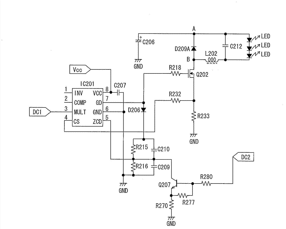
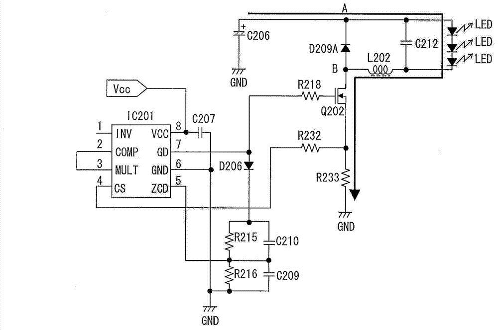
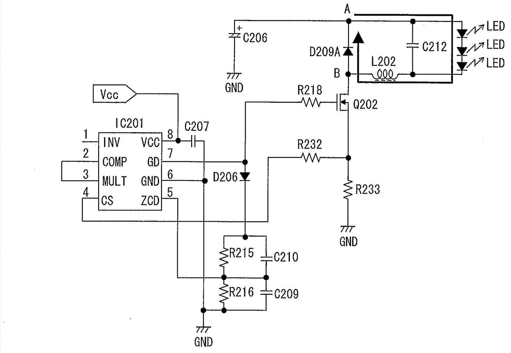
[0035] figure 2 with image 3 It is a circuit diagram showing a typical structure of an LED drive circuit using a conventional PWM dimming method. This circuit shows a rated current circuit, and in this rated current circuit, L6562 (trade name) manufactured by STMicro is used as a control IC. Figure 4 said in the use of figure 2 and image 3 The current flowing through the LED when the LED driving circuit shown is driving the LED. This LED drive circuit includes a step-down converter type DC / DC converter (hereinafter simply referred to as “inverter”) including an inductor L202 , a transistor Q...


PUM


Abstract

An LED drive circuit of the present invention carries out, by use of a DC-to-DC converter (L202,Q202,D209A,C212), light control of an LED. The light control is carried out, in a region where a light control level is equal to or greater than a certain light control level, by a DC light control method for adjusting a pulse height of an LED drive current. The light control is carried out, in a region where a light control level is equal to or less than the certain light control level, by a PDM light control method for adjusting an off period of oscillation of the DC-to-DC converter.

Description

technical field [0001] The present invention relates to a buck converter (buck converter) type or a buck boost converter (buck boost converter) type LED (Light Emitting Diode; light emitting diode) drive circuit. Background technique [0002] Referring to the LED driving circuit, the generally well-known LED driving circuit uses a DC / DC converter to provide a rated current to the LED, and changes the current value to control the dimming of the LED. As a method of supplying a rated current to an LED, an output current is detected by a resistor or the like, and a voltage is fed back so that a desired current can flow (for example, Patent Document 1). However, in general, this method still suffers from flicker in the sub-10% dimming region. [0003] In order to prevent the above problems, it is possible to use a step-down converter or a step-down converter to perform dimming by means of PWM (pulse width modulation; pulse width modulation) dimming (for example, Patent Document ...

Claims


Application Information

Patent Timeline
Patent Type & Authority Applications(China)
IPC IPC(8): H05B37/02H05B44/00
CPCH05B33/0818H05B45/3725H05B45/375
Inventor 村上幸三郎
Owner SHARP KK
Why Eureka
Try Eureka