
Patsnap Eureka
For R&D, Patsnap Eureka makes reading and utilizing patents & technical documents easy.
Patsnap Eureka AIR
Designed for self-driven R&D workflows. Generate viable solutions, solve complex R&D challenges, empower your innovation with AI.

Patsnap Eureka Materials
Designed for material experts only. Revolutionize your material R&D, from search, analyze, to developing new materials.

TechResearch
Generate reliable direction feasibility study reports for your R&D in just a few steps.

TechSeek
Discover and master advanced knowledge NOW. Basics, ideas, possibilities, all at once.

TechMind
As an expert in R&D Theories, TechMind can generates customized viable solutions instantly.

TechRisk
Analyze your overall solution with one click, know your potential R&D risks in advance.

TechMonitor
Get weekly tech updates, stay abreast of the latest tech innovations and key insights.
Cooled mr coil arrangement
A coil layout and coil technology, applied in the direction of measuring devices, measuring magnetic variables, instruments, etc., can solve problems such as air bubbles in the epoxy resin filling area, achieve the effect of increasing rms current, avoiding overheating, and improving the maximum
- Summary
- Abstract
- Description
- Claims
- Application Information
AI Technical Summary
Problems solved by technology
Method used
Image

Examples
Embodiment Construction
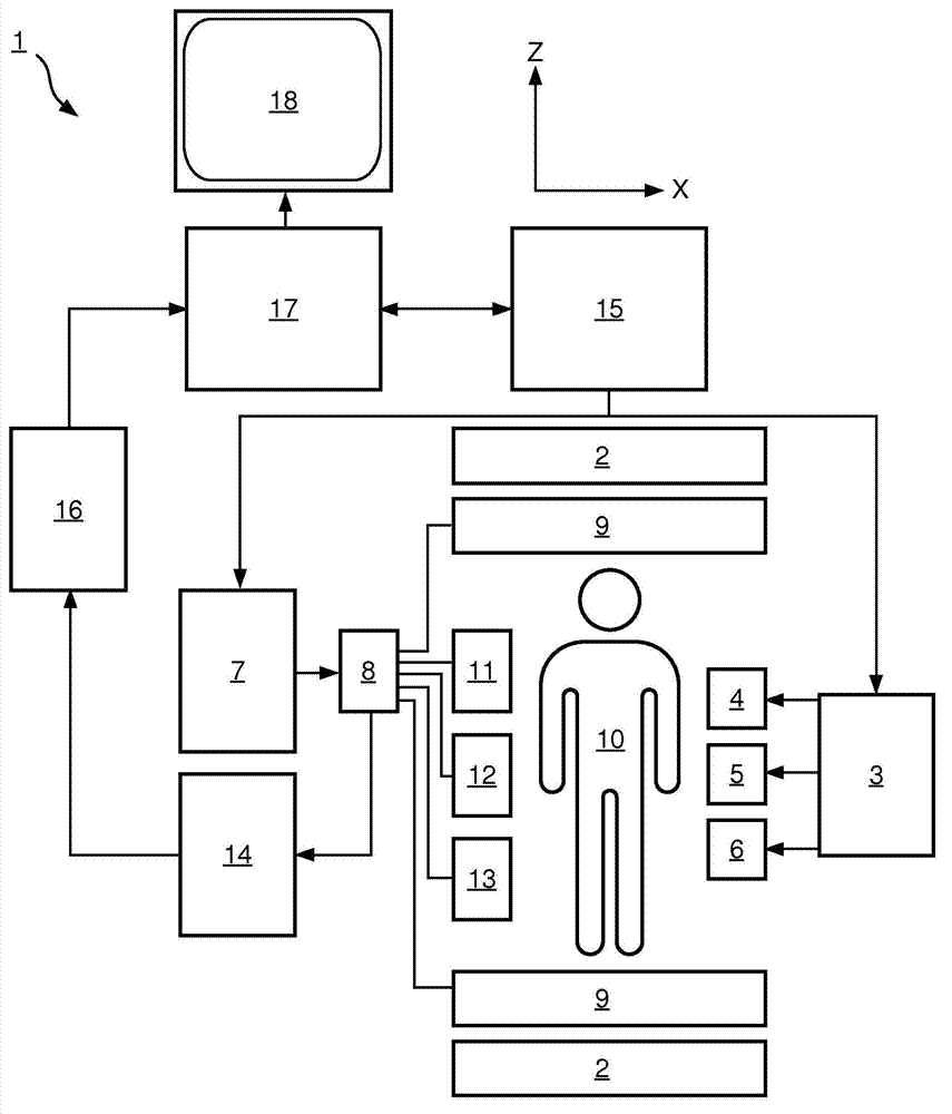
[0033] refer to figure 1 , shows a schematic diagram of the MR imaging system 1 . The system comprises superconducting or resistive main magnet coils 2, thereby establishing a substantially uniform temporally constant main magnetic field B along the z-axis through the examination volume 0 .
[0034] Magnetic resonance generation manipulation systems apply a series of RF pulses and switched magnetic field gradients to invert or excite nuclear magnetic spins, induce magnetic resonance, refocus magnetic resonance, manipulate magnetic resonance, spatially or otherwise encode magnetic resonance , saturating spins, etc., to perform MR imaging.
[0035] More specifically, the gradient pulse amplifier 3 applies current pulses to selected ones of the whole body gradient coils 4, 5, 6 along the x, y and z axes of the examination volume. The RF transmitter 7 transmits RF pulses or pulse packets to the RF antenna 9 via the send / receive switch 8 to transmit the RF pulses into the examin...
PUM
 Abstract
Description
Claims
Application Information
 - R&D Engineer
- R&D Manager
- IP Professional
- Industry Leading Data Capabilities
- Powerful AI technology
- Patent DNA Extraction
Browse by: Latest US Patents, China's latest patents, Technical Efficacy Thesaurus, Application Domain, Technology Topic, Popular Technical Reports.
© 2024 PatSnap. All rights reserved.Legal|Privacy policy|Modern Slavery Act Transparency Statement|Sitemap|About US| Contact US: help@patsnap.com