Eureka AIR delivers breakthrough ideas for toughest innovation challenges, trusted by R&D personnel around the world.

Vertical grinding mill

A technology of vertical grinding and grinding zone, applied in the direction of grain processing, etc., can solve the problems of increasing the contact surface of grinding roller and grinding disk, grinding disk and grinding roller wear, small gap between grinding roller and grinding disk, and different thickness of material layer. The effect of less sweeping parts, efficient grinding, and high powder selection efficiency

Active Publication Date: 2015-04-29
ANHUI CONCH KAWASAKI ENERGY CONSERVATION EQUIP
View PDF10 Cites 2 Cited by
  • Summary
  • Abstract
  • Description
  • Claims
  • Application Information

AI Technical Summary

Problems solved by technology

At present, most of the vertical mill structures in China are integrally cast flat grinding discs, which have the following problems in operation: 1) With the rotation of the grinding disc during normal operation, the raw materials are dispersed on the grinding disc under the influence of centrifugal force, but due to the flat Grinding disc, the uneven distribution of raw materials on the grinding disc leads to different material layer thicknesses on various parts of the grinding disc, which can easily lead to an increase in the load of the main motor of the vertical mill and cause the entire vertical mill system to trip; 2) Since it is a flat grinding disc, the When grinding, the grinding track of the grinding roller is perpendicular to the grinding disc, so that the gap between the grinding roller and the grinding disc is small, and the contact surface between the grinding roller and the grinding disc is increased in the case of uneven distribution of the material layer, which increases the wear of the grinding disc and the grinding roller

Method used


Image

  • Vertical grinding mill
  • Vertical grinding mill
  • Vertical grinding mill

Examples


Embodiment Construction

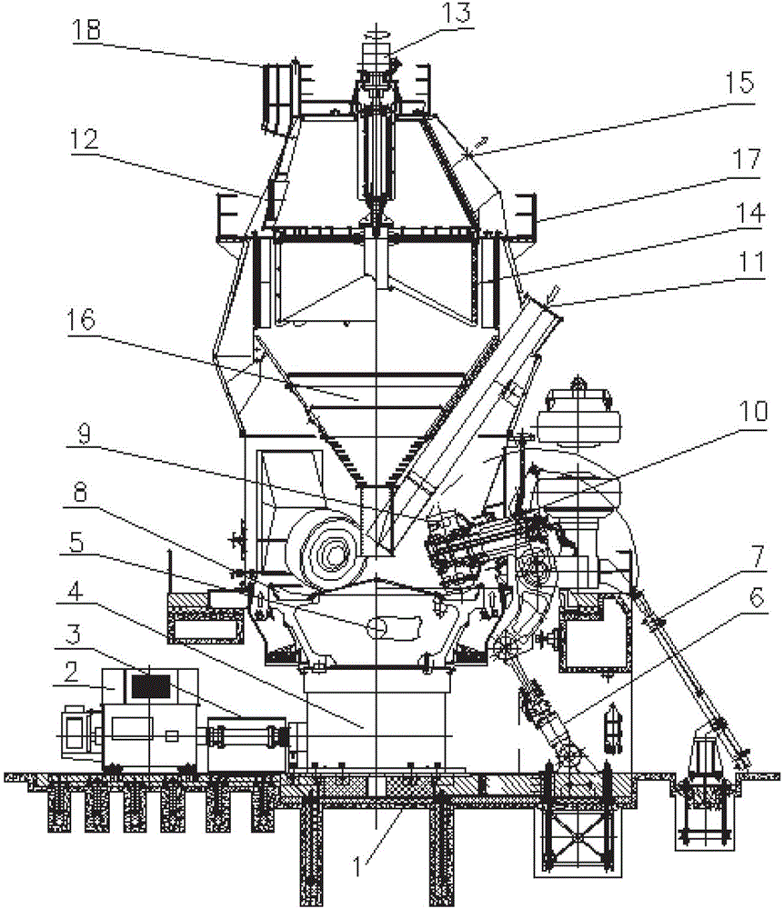
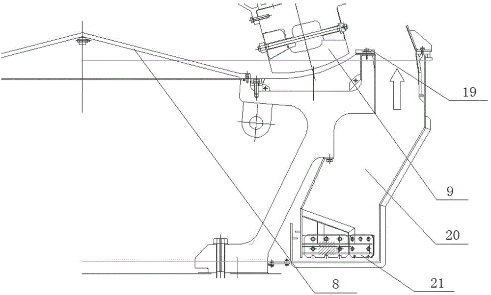
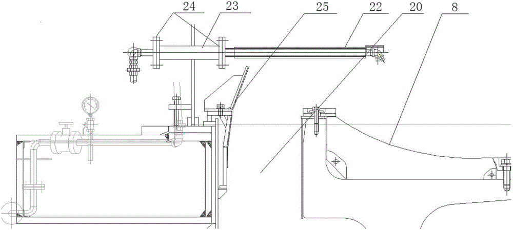
[0025] see figure 1 It can be seen that the vertical mill body is fixed on the concrete foundation 1, and the grinding disc 8 is installed on the reducer 4 at the bottom of the vertical mill body. The reducer 4 is driven by the main motor through the coupling 3, and drives the grinding disc 8 to rotate. The center of the grinding disc 8 is non-grinding area It is in the shape of an upward convex cone, and its edge grinding area (grinding plate liner) is an arc surface that gradually rises outward. The area is conical, and when the material falls on the grinding disc 8, it will enter the surrounding grinding area evenly with the centripetal force of the grinding disc 8 and the sliding force of the cone surface for grinding. The grinding roller 9 is supported by the rocker arm 10, and extends from the side of the vertical mill to the top of the grinding area of ​​the grinding table 8. There are usually four grinding rollers 9, all of which are fixed obliquely downward, so that t...


PUM


Abstract

The invention discloses a vertical grinding mill, wherein a vertical grinding mill body is fixed on a concrete foundation; a grinding table is driven by a rotary power source and horizontally placed at the bottom of the vertical grinding mill; a discharging clearance exists between the grinding table and the inner wall of the vertical grinding mill; a non-grinding region in the center of the grinding table is of an upwards-raised cone; an edge grinding region is of an arc surface which is gradually raised upwards; and a grinding roller extends from the side of the vertical grinding mill to the upside of the grinding region of the grinding table and obliquely fixed downwards. The vertical grinding mill provided by the invention has the advantages of small grinding table diameter, high grinding table rotating sped, high work efficiency, low energy consumption and the like.

Description

technical field [0001] The invention relates to a kind of grinding (drying and grinding) used in cement, building materials, metallurgy, electric power and chemical industries and other materials. Background technique [0002] The vertical mill is mainly used for grinding cement raw materials, cement, coal and slag. It continuously provides raw materials for the production of the factory, so its operating cycle must be long and the failure rate must be low, which makes the structure of each component of the vertical mill must be strong. durable. At present, most of the domestic vertical mill structures are mostly flat grinding discs cast integrally, and there are the following problems in operation: 1) With the rotation of the grinding disc during normal operation, the raw materials are dispersed on the grinding disc under the influence of centrifugal force, but due to the flat Grinding disc, the uneven distribution of raw materials on the grinding disc leads to different m...

Claims


Application Information

Patent Timeline
Patent Type & Authority Patents(China)
IPC IPC(8): B02C15/02B02C23/20
Inventor 汪宁肖杰玉孙斌张树琛卫明周健
Owner ANHUI CONCH KAWASAKI ENERGY CONSERVATION EQUIP
Why Eureka
Eureka Blog
Learn More