Shearing mechanism of resin-based fiber placement system

A shearing mechanism, resin-based technology, applied in metal processing and other directions, can solve the problems that the fiber belt is easy to fall into the channel, the impact of the entire mechanism, and the short service life of the blade, so as to achieve convenient application, improve reliability, and reduce cutting force. Effect

Inactive Publication Date: 2013-03-13
XI AN JIAOTONG UNIV
View PDF2 Cites 19 Cited by
  • Summary
  • Abstract
  • Description
  • Claims
  • Application Information

AI Technical Summary

Problems solved by technology

The "cutting" method is easy to cause impact on the whole mechanism and damage the fiber channel and blade. The blade has a short service life and requires a large cutting force. At the same time, the fiber band is easy to fall into the channel after being cut, which is not conducive to re-transportation; and The structure of the "cutting" method using the gap between two blades is more complicated, which is not conducive to integration in the wire laying head with a smaller structural size, the required cutting force is also large, the blades are more worn and damaged, and the service life of the blades is short.

Method used


Image

  • Shearing mechanism of resin-based fiber placement system
  • Shearing mechanism of resin-based fiber placement system
  • Shearing mechanism of resin-based fiber placement system

Examples


Embodiment Construction

[0024] An embodiment of the present invention will be described in detail below in conjunction with the accompanying drawings.

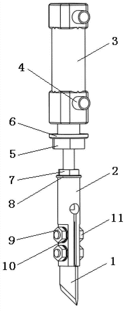
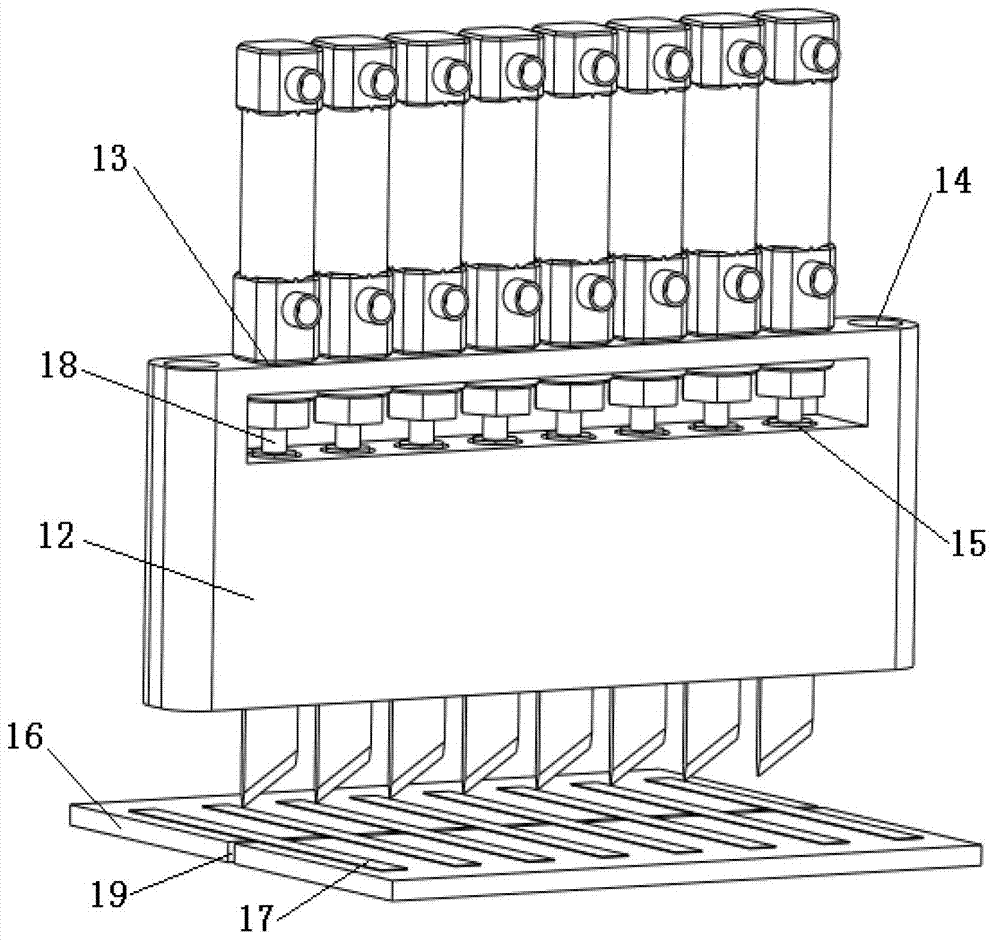
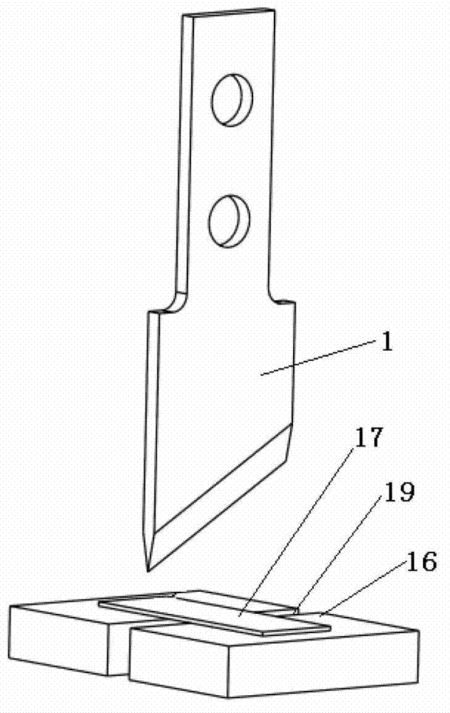
[0025] Such as figure 1 , 2 , 3, 4, and 5 show that the mechanism mainly includes an oblique blade 1, a handle block 2, a cylinder frame 12, an anvil 16, an anvil slit 19 and a driving element cylinder 3 of the device; in this mechanism, the oblique blade 1 The bolt 11, the third spring washer 10, the third nut 9 are connected with the handle block 2, the handle block 2 is connected with the cylinder rod 18 through the second spring washer 8, the second nut 7, and the cylinder 3 is connected by the second spring washer 8 and the second nut 7. A nut 5 and the first spring washer 6 are installed in the first installation hole 13 on the cylinder frame 12, and finally the whole shearing mechanism is integrated in the silk laying head of the silk laying system through the second installation hole 14. please combine image 3 As shown, in the silk laying...


PUM

PropertyMeasurementUnit
angleaaaaaaaaaa

Abstract

The invention discloses a shearing mechanism of a resin-based fiber placement system, which is applied to the field of fiber placement manufacturing of resin-based composite material members. The shearing mechanism mainly comprises the following elements: a bevel-connection blade, a knife handle block, a cylinder frame, a chopping board, a chopping board gap and a device driving element cylinder. The bevel-connection blade is connected with the knife handle block which is connected with a cylinder rod, the cylinder is arranged on the cylinder frame, and finally, the whole shearing mechanism is integrated into a fiber placement head of the fiber placement system through a mounting hole. In fiber placement process, a fiber prepreg tape is conveyed to enter the chopping board, the gas is introduced into the cylinder, the knife handle block and the bevel-connection blade fast move downwards through a via hole in the cylinder frame under the driving of the cylinder rod, thereby further cutting the fiber prepreg tape placed on the chopping board by the bevel-connection blade.

Description

Technical field: [0001] The patent of the invention relates to the field of resin-based composite material manufacturing, which is used in resin-based fiber laying equipment, and specifically relates to a shearing mechanism based on a resin-based fiber laying system. Background technique: [0002] Resin-based fiber-reinforced composite materials have the advantages of low density, high specific strength, high specific modulus, high fatigue resistance and corrosion resistance, and integration of structure and function, design and manufacturing integration, etc. It has very broad application prospects in aerospace, wind power blades, automobiles and other fields. Fiber laying technology is an automatic and high-quality manufacturing technology for resin-based fiber-reinforced composite materials. It is a fully automated manufacturing technology developed on the basis of existing winding and automatic tape laying technologies. Fiber laying technology inherits the advantages of...

Claims


Application Information

Patent Timeline
Patent Type & Authority Applications(China)
IPC IPC(8): B29C70/54B26D1/04B26D5/12
Inventor 段玉岗李涤尘余陈伟张小辉李超
Owner XI AN JIAOTONG UNIV
Why Eureka
Try Eureka