Liquid fuel gasification device and burner

A liquid fuel, gasification device technology, applied in the burner, combustion method, combustion type, etc., to achieve good combustion effect, high combustion efficiency, and reduce carbon precipitation

Active Publication Date: 2016-02-17
CHONGQING DAWEI ENERGY
View PDF6 Cites 0 Cited by
  • Summary
  • Abstract
  • Description
  • Claims
  • Application Information

AI Technical Summary

Problems solved by technology

[0005] The technical problem to be solved by the present invention is to propose a liquid fuel gasification device and burner, the liquid fuel gasification device can not only gasify liquid fuel, but also has the advantages of strong gasification capacity, high gasification efficiency and sufficient gasification , and solve the carbon blockage problem in the gasification process, and can work stably for a long time; and the liquid fuel burner using the liquid fuel gasification device has the advantages of good combustion effect and high combustion efficiency, and can be suitable for industrial applications

Method used


Image

  • Liquid fuel gasification device and burner
  • Liquid fuel gasification device and burner

Examples


no. 1 example

[0024] First, the specific implementation of the liquid fuel gasification device of the present invention will be described in detail.

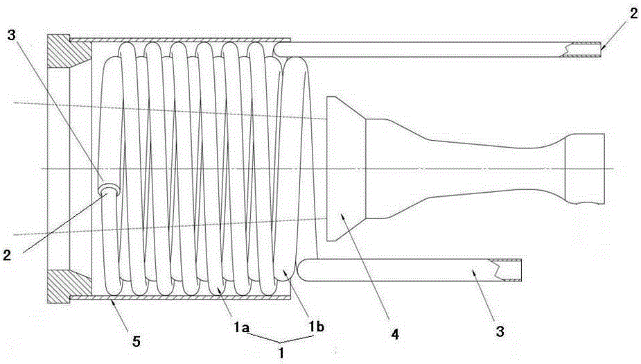
[0025] Such as figure 1 Shown is a schematic structural diagram of an embodiment of the liquid fuel gasification device of the present invention. The liquid fuel gasification device of this embodiment includes at least two layers of spiral gasification coils 1 stacked together, each layer of spiral gasification coils 1 is provided with a fuel inlet 2 and a fuel outlet 3, adjacent to each other In the layered spiral gasification coil 1, the fuel outlet 3 of the outer spiral gasification coil 1 is connected to the fuel inlet 2 of the inner spiral gasification coil 1, and the innermost spiral gasification coil The center of the tube 1 is provided with a heat source 4 for vaporizing liquid fuel, the fuel inlet 2 of the outermost spiral gasification coil 1 is externally connected to the liquid fuel storage device, and the fuel outlet of the inner...

no. 2 example

[0031] The specific implementation of the liquid fuel burner of the present invention will be described in detail below.

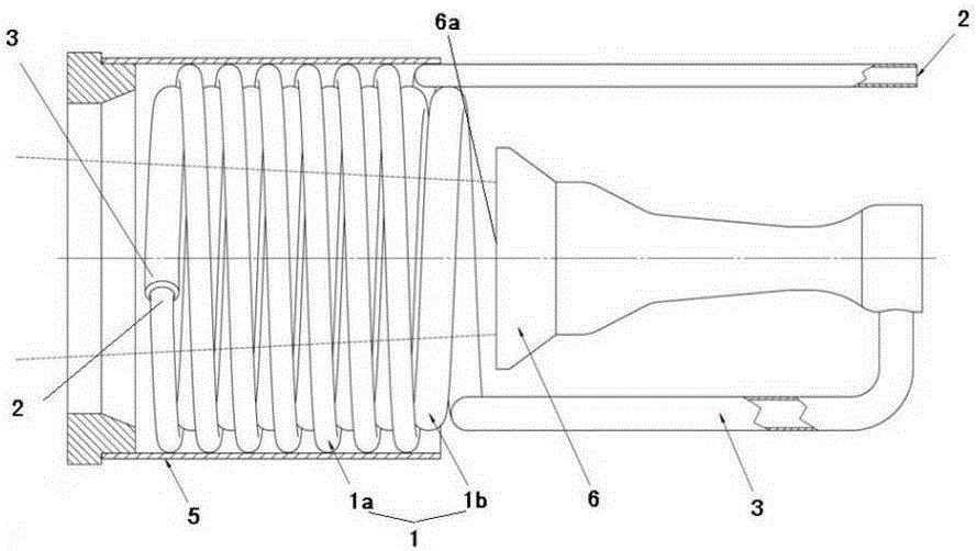
[0032] Such as figure 2 Shown is a schematic structural view of an embodiment of the liquid fuel burner of the present invention. The liquid fuel burner of this embodiment includes the liquid fuel gasification device and the combustion device 6 described in the first embodiment, the fuel inlet of the combustion device 6 is connected with the fuel outlet 3 of the spiral gasification coil 1 located in the innermost layer , that is, the fuel inlet of the combustion device 6 of this embodiment is connected with the fuel outlet 3 of the inner spiral gasification coil 1b.

[0033] The liquid fuel burner of this embodiment, by adopting the liquid fuel gasification device of the first embodiment, can fully gasify the liquid fuel, and can prevent the problem of carbon clogging, that is, realize the liquid gasification combustion of the liquid fuel burner, The ut...


PUM


Abstract

The invention discloses a liquid fuel gasification device, which comprises at least two layers of spiral gasification coils stacked together. Each layer of spiral gasification coils is provided with a fuel inlet and a fuel outlet. In the gasification coil, the fuel outlet of the outer spiral gasification coil is connected to the fuel inlet of the inner spiral gasification coil, and the center of the innermost spiral gasification coil is provided with a gas Heat source for liquefied liquid fuel. The invention also discloses a liquid fuel burner, which comprises the above liquid fuel gasification device and a combustion device. The fuel inlet of the combustion device is connected with the fuel outlet of the innermost spiral gasification coil. The liquid fuel gasification device can not only gasify liquid fuel, but also has the advantages of strong gasification capacity, high gasification efficiency and sufficient gasification, and solves the problem of carbon blockage in the gasification process; the liquid fuel burner has a combustion The advantages of good effect and high combustion efficiency can be suitable for industrial applications.

Description

technical field [0001] The invention belongs to the technical field of burners, in particular to a liquid fuel gasification device capable of gasifying liquid fuel and a liquid fuel burner using the liquid fuel gasification device. Background technique [0002] Alcohol-based liquid fuel is a low calorific value liquid fuel. Its combustion methods include liquid surface direct combustion, liquid spray combustion and liquid gasification combustion. For low calorific value liquid fuels, the flame effects of liquid surface direct combustion or liquid spray combustion are both It is very poor, and basically cannot meet the combustion requirements of industrial furnaces. Although the combustion effect of liquid gasification combustion is good and the efficiency is high, the gasification technology of liquid fuel is a difficult problem. [0003] Although the currently used liquid fuel vaporizers can achieve gasification and combustion of liquid fuels to a certain extent, there are ...

Claims


Application Information

Patent Timeline
Patent Type & Authority Patents(China)
IPC IPC(8): F23D11/44F23D11/00
Inventor 冯敏昌刘俊幸大华任建伟杨毅
Owner CHONGQING DAWEI ENERGY
Why Eureka
Try Eureka