

Full-flow-point rapid detection device for water meter
Patent Information
- Authority / Receiving Office
- CN · China
- Current Assignee / Owner
- LIANYUNGANG LIANLI WATER METER
- Publication Date
- 2013-03-13
- Estimated Expiration
- Not applicable · inactive patent
Smart Images
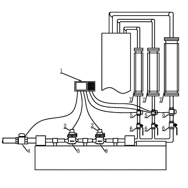
Figure 1 
Figure 2 
Figure 3
Abstract
Description
technical field
[0001] The invention relates to a water meter error detection technology, in particular to a fast detection device for the full flow point of the water meter. Background technique
[0002] At present, in the production process of water meters, especially in the production process of large quantities of water meters, the test of each flow point is mainly carried out by detection devices with different functions, such as: volumetric water meter detection devices or computer detection devices are often used for large flow and nominal flow , while the boundary flow and small flow often use a series detection device to realize the detection of the error of each flow point of the water meter. In the above method, the performance of the water meter is affected by factors such as equipment working conditions and human factors in the actual production process, and because the serial detection device cannot adjust the water meter in real time, unqualified water meters...