
Refractive index measurement method based on double-fiber point diffraction phase-shifting interference

A point diffraction phase shift and measurement method technology, applied in the field of optical precision measurement, can solve problems such as restricting development, and achieve the effect of reducing waste, efficient and rapid real-time monitoring

Inactive Publication Date: 2015-10-21
BEIJING INSTITUTE OF TECHNOLOGYGY
View PDF2 Cites 0 Cited by
  • Summary
  • Abstract
  • Description
  • Claims
  • Application Information

AI Technical Summary

Problems solved by technology

Interferometry has high precision and non-destructiveness, and has become a research hotspot in recent years, but some technical means limit its development, such as fringe counting and angle control measurement technology, etc.

Method used


Image

  • Refractive index measurement method based on double-fiber point diffraction phase-shifting interference
  • Refractive index measurement method based on double-fiber point diffraction phase-shifting interference
  • Refractive index measurement method based on double-fiber point diffraction phase-shifting interference

Examples


Embodiment Construction

[0025] The specific implementation manner of the present invention will be described in further detail below in conjunction with the accompanying drawings.

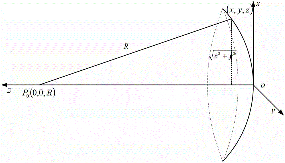
[0026] The basic principle of the present invention is based on the shearing interference of point light sources. Such as figure 1 As shown, the point light source P located at coordinates (0,0,R) 0 The spherical wave is diffracted, the exit pupil surface is located on the xoy plane, and the exit pupil center is located at the origin O of the xyz coordinate system. Assuming that the radius of curvature of the spherical wave is R, the equation of the spherical wave on the exit pupil surface is:

[0027] w ( x , y ) = z = R - R 2 - ( x 2 + ...


PUM


Abstract

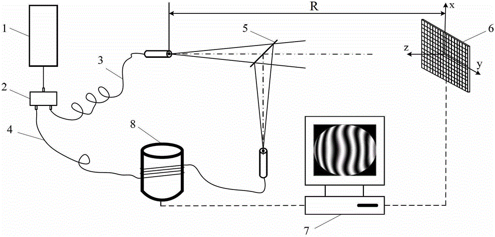
The invention discloses a refractive index measurement technology and a device based on dual-fiber point-diffraction phase-shift interference, and belongs to the technical field of optical measurement. The refractive index measurement technology comprises the following steps: firstly regulating a measurement fiber so that the measurement fiber is conjugated with a reference fiber relative to a film spectroscope, wherein no interference fringe is positioned on a CCD (Charge Coupled Device) camera at the time; acquiring and processing a phase-shift interference pattern to obtain the fitting coefficients of the wave disparity of a pupil plane; then inserting a measured sample processed into a parallel plate between the measurement fiber and the film spectroscope, so as to change the optical path difference of the measurement fiber and the reference fiber, wherein concentric ring-shaped interference fringes appear on the CCD camera at the time; acquiring and processing the phase-shift interference pattern to obtain the fitting coefficients of the wave disparity of the pupil plane again; computing the axial displacement of a fiber point light source after the parallel plate is introduced by measuring the distance from the reference fiber to the CCD camera; and further computing the refractive index of the measured sample on the basis of the thickness measurement of the parallel plate. The refractive index measurement device disclosed by the invention is simple in structure and can accurately, easily and conveniently measure the refractive index of a solid or liquid.

Description

technical field [0001] The invention belongs to the technical field of optical precision measurement, and relates to a refractive index measurement technology and device, which can realize accurate measurement of the refractive index of solid or liquid on the basis of double-fiber point diffraction phase-shifting interference. Background technique [0002] One of the important physical parameters of a transparent substance is its refractive index to light, and the measurement of the refractive index of light is the basis for studying other optical properties. In theoretical research and engineering practice, we often measure the refractive index of glass, transparent engineering plastics, transparent liquids, etc., so as to understand their optical properties, purity, concentration and other characteristics. However, with the continuous development of lithography objective lens, infrared optical system, optical fiber communication, medicine, new materials and other technolog...

Claims


Application Information

Patent Timeline
Patent Type & Authority Patents(China)
IPC IPC(8): G01N21/45
Inventor 陈凌峰郭晓菲郝金剑
Owner BEIJING INSTITUTE OF TECHNOLOGYGY
Learn More