

Switch magnetic flux motor for directly driven electric vehicle
A switching flux motor, electric vehicle technology, applied in vehicle components, control devices, transportation and packaging, etc., can solve the problems of complex structure, large volume, harsh use environment, etc., achieve simple rotor structure, compact overall structure, and use Maintenance-friendly effect
- Summary
- Abstract
- Description
- Claims
- Application Information
AI Technical Summary
Problems solved by technology
Method used
Image

Examples
Embodiment Construction
[0018] The present invention will be described in detail below in conjunction with the accompanying drawings.
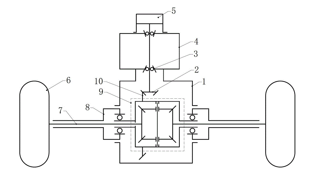
[0019] refer to figure 1 , a switched flux motor for a direct drive electric vehicle, comprising a switched flux motor 4, a resolver 5, a final reducer, a differential 9, a half shaft 7, an axle housing 8 and driving wheels 6. The drive axle of the electric vehicle adopts an integral axle structure, the final reducer, the differential 9 and the axle shaft 7 are arranged in the axle housing 8, and the two ends of the axle housing 8 are connected to two driving wheels 6. The power supply of the whole vehicle is provided by the storage battery, and the DC power provided by the storage battery is input to the switched flux motor 4 after being converted by the controller. The output torque of the switched flux motor 4 is decelerated by the main reducer, and then transmitted to the differential 9, and the differential 9 performs differential speed according to the driving...
PUM
 Abstract
Description
Claims
Application Information