Method and equipment for controlled directional solidification and purification of polycrystalline silicon through taking tailing by graphite tube

A technology of directional solidification and graphite tubes, applied in chemical instruments and methods, silicon compounds, inorganic chemistry, etc., can solve the problems of reduced industrial production costs, high cutting equipment costs, and affecting purification effects, etc. Energy consumption and the effect of reducing process links

Inactive Publication Date: 2013-03-20
QINGDAO NEW ENERGY SOLUTIONS
View PDF4 Cites 7 Cited by
  • Summary
  • Abstract
  • Description
  • Claims
  • Application Information

AI Technical Summary

Problems solved by technology

In the subsequent slow cooling process, the impurities in the high-concentration area will diffuse to the low-concentration area, so that the purity of silicon will gradually decrease with the prolongation of the holding time, which affects the purification effect, and in this case, the tail that needs to be removed The waste is as high as 25%~35%, and the finished product rate is only 65-75%
At the same time, due to the relatively high hardness of silicon, high-power cutting equipment is needed to separate the purified silicon ingot from the ingot tailings with high impurity content at the tail. At present, wire cutting and diamond saw band cutting are generally used for cutting, but cutting The high cost of equipment and the large consumption of saw bands are not conducive to the reduction of industrial production costs. At present, there are few effective methods in China to facilitate the removal of tailings

Method used


Image

  • Method and equipment for controlled directional solidification and purification of polycrystalline silicon through taking tailing by graphite tube

Examples


Embodiment 1

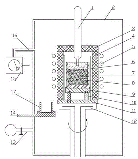
[0023] Such as figure 1 The equipment used in the method of directional solidification and purification of polysilicon by graphite tube tailing is shown. The outer wall is composed of a vacuum chamber 2, and a vacuum pipeline 16 is installed on the outer wall. One end of the vacuum pipeline 16 is connected to a vacuum pump group 15.

[0024] A ventilation pipeline 13 is fixedly installed on the outer wall, and a water-cooled support rod 14 is installed movably. The inside of the water-cooled support rod passes cooling water. The water-cooled crucible 17 is installed on the water-cooled support rod, and the cooling water is used for cooling the water-cooled crucible.

[0025] The water cooling plate 12 is movable and sealed at the bottom of the vacuum chamber 2. The graphite plate 11 is placed on the top of the water cooling plate. There are holes on the graphite plate 11. One end of the graphite pillar 10 is nested and connected with the graphite plate 11 through the hole, and ...

Embodiment 2

[0030] Use the equipment described in Example 1 to take the tailings and carry out directional solidification to purify polysilicon. First, add silicon material with a purity of 99.5% to the crucible 7 with 90% of the volume of the crucible, close the ventilation line 13, and turn on the vacuum pump group 15. The vacuum degree in the vacuum chamber 2 is pumped to 10Pa, close the vacuum pump group 15, open the ventilation pipeline, fill the vacuum chamber 2 with 99.93% argon until the pressure reaches 100Pa, and close the ventilation pipeline;

[0031]The second step of smelting and solidification: turn on the power, use the induction coil 5 and the graphite heating element 6 to heat the silicon material in the crucible 7 to 1450 ° C until it is completely melted into a silicon melt, keep it at this temperature for 30 minutes, and pull it vertically downward The water cooling plate 12 makes the silicon melt in the crucible 7 move vertically downward at a constant speed at a spee...

Embodiment 3

[0034] Use the equipment described in Example 1 to take tailings and carry out directional solidification to purify polysilicon. First, add silicon material with a purity of 99.7% to the crucible 7 with a volume of 93% of the crucible, close the ventilation line 13, and turn on the vacuum pump group 15. The vacuum in the vacuum chamber 2 is pumped to 1Pa, the vacuum pump unit 15 is turned off, the ventilation pipeline is opened, and 99.97% argon is filled into the vacuum chamber 2 until the pressure reaches 800Pa, and the ventilation pipeline is closed;

[0035] The second step of smelting and solidification: turn on the power, use the induction coil 5 and the graphite heating element 6 to heat the silicon material in the crucible 7 to 1550 ° C until it is completely melted into a silicon melt, keep it at this temperature for 45 minutes, and pull it vertically downward The water cooling plate 12 makes the silicon melt in the crucible 7 move vertically downward at a constant spe...


PUM


Abstract

The invention belongs to the technical field of metallurgy purification, and particularly relates to a method and equipment for directional solidification and purification of polycrystalline silicon through taking tailing. According to the method, under the inert gas shielding environment, abluent silicon is melted so as to carry out directional solidification; ingot pulling is stopped when solidification is completed by 85-90%, a graphite tube is stretched into surplus melt silicon, then inert gas is led into a vacuum chamber, so that the surplus melt silicon enters the graphite pipe under the action of pressure difference and ingot pulling is continuously carried out, after the upper end of a crucible leaves a heating area, the water cooled crucible is stretched below the graphite tube, inert gas is stopped being led into the vacuum chamber, the vacuum chamber is vacuumed, the surplus melt silicon in the graphite tube falls into the water cooled crucible to be cooled and solidified; the power is cut off so as to stop heating, and cast ingot solidified in a crucible is silicon cast ingot of high purity. Due to the method, back-diffusion of impurity is prevented, technology processes are reduced, and the yield of cast ingot is improved. The equipment is convenient to improve and install, is easy to operate, can effectively remove impurities accumulated at the tail of the cast ingot, saves production period and cost, and is applicable to industrial production.

Description

technical field [0001] The invention belongs to the technical field of metallurgical purification, and in particular relates to a method and equipment for directional solidification and purification of polysilicon by tailing material extraction. Background technique [0002] The purification of silicon raw materials is an important link in the solar photovoltaic industry chain. The rapid development of the photovoltaic industry depends on high-efficiency and low-cost purification methods. Directional solidification technology has been widely used in many fields of metal purification, and has achieved remarkable results. In the process of purifying silicon raw materials, metal impurities whose segregation coefficient is far less than 1 will be enriched in the liquid phase during the directional solidification process and finally removed. This method is one of the key links in the current metallurgical preparation of solar-grade polysilicon, and is the most effective method f...

Claims


Application Information

Patent Timeline
Patent Type & Authority Applications(China)
IPC IPC(8): C01B33/037
Inventor 谭毅姜大川安广野石爽胡志刚
Owner QINGDAO NEW ENERGY SOLUTIONS
Why Eureka
Try Eureka