Sinter feeding system and method for improving burden distribution of blast furnace

A technology for sinter and blast furnace, applied in blast furnace, blast furnace details, blast furnace parts and other directions, can solve the problems of high density of material layer, loss, green core, etc., to achieve flexible adjustment, control particle size segregation, and improve air permeability.

Inactive Publication Date: 2013-03-20
MCC NORTH (DALIAN) ENG TECH CO LTD
View PDF4 Cites 12 Cited by
  • Summary
  • Abstract
  • Description
  • Claims
  • Application Information

AI Technical Summary

Problems solved by technology

[0002] In blast furnace smelting production, sinter accounts for about 85% of the furnace charge, and the particle size is 5-150mm. Therefore, the particle size and distribution of sinter determine the air permeability of the material layer in the blast furnace cavity. Among them, large-scale finished products >20mm are sintered The ore part accounts for about 52% of the finished sinter, and the 5-20mm small finished sinter part accounts for about 48% of the finished sinter. The grades are mixed together and sent to the blast furnace by the same belt conveyor. After the sinter is sent into the blast furnace, it forms a "w"-shaped cloth. Relatively smooth, sinter particle size varies to form gaps between materials, while small-sized sinter aggregates in the middle of the material layer, resulting in high density of the material layer, forcing most of the hot air blown from the bottom of the blast furnace from the edge of the material layer, along the furnace wall Passing through the large-grained sinter forms an "edge" effect, that is, the large-grained sinter near the furnace wall is overheated, and the middle part of the material layer cannot be burned through in time, resulting in the "core" phenomenon, which not only affects the production of the blast furnace, but also causes A large amount of hot air cannot be effectively used and lost from the large finished sinter

Method used


Image

  • Sinter feeding system and method for improving burden distribution of blast furnace

Examples


Embodiment Construction

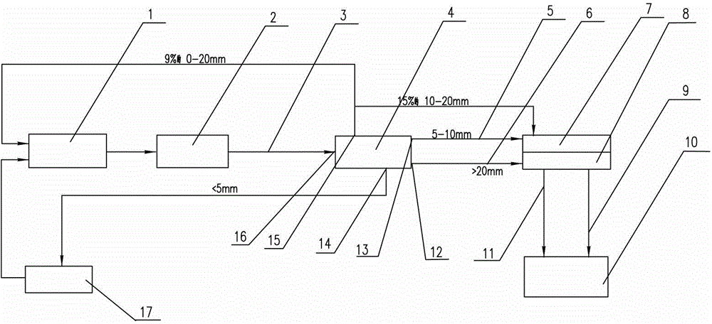
[0011] The present invention will be further described below in conjunction with accompanying drawing.

[0012] Such as figure 1 As shown, the sinter feeding system for improving blast furnace material distribution of the present invention includes a sinter feeding device 1, an annular cooler 2, a sinter conveying belt conveyor 3, a finished product trough, and a material distribution system between the finished product trough and the blast furnace roof. The finished ore conveying belt machine between the devices is characterized in that a screening machine 4 is provided between the sintered ore conveying belt 3 and the finished product ore tank, and the described screening machine 4 is a three-stage screening machine, and the three-stage screening machine is equipped with There are feed inlet 16, large-size finished ore discharge outlet 12 corresponding to the product on the primary sieve > 20mm, and 10-20mm finished ore medium-sized bottom layer discharge outlet 15 correspon...


PUM


Abstract

The invention relates to a sinter feeding system and method for improving burden distribution of a blast furnace. The feeding system is characterized in that a three-level sieving machine is arranged between a sinter conveying rubber belt and finished sinter grooves; a feeding hole and four discharge holes are arranged on the three-level sieving machine; and the finished sinter grooves are two storage grooves in big and small particle sizes. The sinters in big and small particle sizes are fed to the blast furnace alternately and orderly by adopting the system. The feeding system and the feeding method have the advantages that the sinters are divided into big and small particle sizes and are fed to the blast furnace alternately and orderly, thus changing the original charging structure of the blast furnace, not only effectively controlling segregation of the charging process and improving the air permeability of the material layer but also enabling burden distribution at the furnace top to be regulated more flexibly and creating favourable conditions for stable and smooth operation of the blast furnace.

Description

technical field [0001] The invention relates to a mineral raw material sinter feeding process, in particular to a sinter feeding system and a feeding method for improving blast furnace material distribution. Background technique [0002] In blast furnace smelting production, sinter accounts for about 85% of the furnace charge, and the particle size is 5-150mm. Therefore, the particle size and distribution of sinter determine the air permeability of the material layer in the blast furnace cavity. Among them, large-scale finished products >20mm are sintered The ore part accounts for about 52% of the finished sinter, and the 5-20mm small finished sinter part accounts for about 48% of the finished sinter. The grades are mixed together and sent to the blast furnace by the same belt conveyor. After the sinter is sent into the blast furnace, it forms a "w"-shaped cloth. Relatively smooth, sinter particle size varies to form gaps between materials, while small-sized sinter aggre...

Claims


Application Information

Patent Timeline
Patent Type & Authority Applications(China)
IPC IPC(8): C21B7/00C21B7/20C21B5/00
Inventor 王明侠朱占军
Owner MCC NORTH (DALIAN) ENG TECH CO LTD
Why Eureka
Try Eureka