Concrete shear wall with continuous annular reinforcement structure

A technology of concrete shear wall and annular steel bar, applied in the direction of structural elements, walls, building components, etc., can solve the problems of poor ductility of shear walls, and achieve the goal of enhancing ductility, avoiding premature collapse, and improving ultimate deformation capacity. Effect

Active Publication Date: 2015-12-09
广州市设计院集团有限公司
View PDF6 Cites 0 Cited by
  • Summary
  • Abstract
  • Description
  • Claims
  • Application Information

AI Technical Summary

Problems solved by technology

[0005] The purpose of the present invention is to provide a concrete shear wall with a continuous annular steel bar structure in order to solve the problem of poor ductility of the shear wall in the prior art. The concrete shear wall has the advantages of simple structure, strong ductility and earthquake resistance. Features of strong performance

Method used


Image

  • Concrete shear wall with continuous annular reinforcement structure
  • Concrete shear wall with continuous annular reinforcement structure
  • Concrete shear wall with continuous annular reinforcement structure

Examples


specific Embodiment 1

[0026] figure 1 with figure 2 It constitutes the specific embodiment 1 of the present invention.

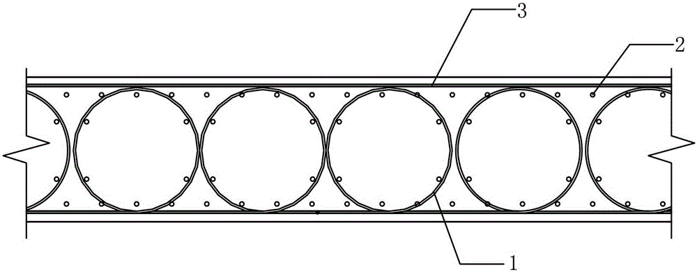
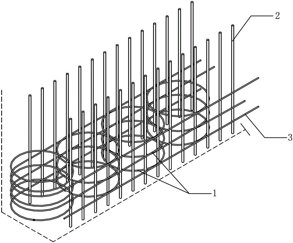
[0027] Reference figure 1 with figure 2 This embodiment includes a wall and a steel frame built into the wall. The steel frame is composed of a horizontal ring-shaped steel bar structure 1 and a longitudinal steel bar structure 2. The horizontal ring-shaped steel bar structure 1 is composed of multiple layers of continuously distributed steel ring , The steel bars in the same layer are connected by 1-2 transverse steel bars 3 to form a whole, that is, a continuously distributed steel ring structure; the longitudinal steel bar structure 2 is composed of multiple longitudinal steel bars, and the longitudinal steel bars are arranged through the steel ring structure It is connected with the reinforcing steel ring and the transverse reinforcing steel 3, and at least part of the longitudinal reinforcing steel is located in the reinforcing steel ring.

[0028] In this embodiment:

[0029] I...

specific Embodiment 2

[0032] image 3 with Figure 4 It constitutes the specific embodiment 2 of the present invention.

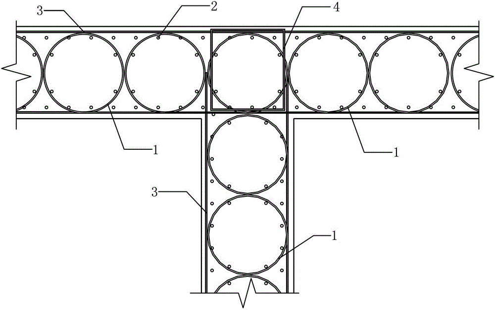
[0033] Reference image 3 with Figure 4 The feature of this embodiment 2 is: the steel frame is a "T"-shaped wall frame with a wing wall, and the transverse ring-shaped steel bar structure 1 in the wing wall is composed of a steel bar wound into a plurality of continuously distributed steel rings , The horizontal ring-shaped steel bar structure 1 in the straight wall is composed of a steel bar that is wound into a plurality of continuously distributed steel rings and extends longitudinally and spirally at the junction with the wing wall to the height of another layer of the horizontal ring-shaped steel bar structure 1; The junction with the wing wall is provided with rectangular hoop and tie bars 4 adapted to the shape of the wall frame to adapt to the shape of the wall frame. The rest is the same as in Example 1.

specific Embodiment 3

[0034] Figure 5 It constitutes the specific embodiment 3 of the present invention.

[0035] Reference Figure 5 The feature of this embodiment 3 is that the steel frame is an "L"-shaped wall frame, and the horizontal ring-shaped steel structure 1 of each layer is composed of a plurality of continuously distributed steel rings that are wound along the "L" shape. The junction of the steel frame is composed of steel bars that are turned to extend; the junction of the "L"-shaped steel frame is provided with rectangular hoop and bracing 4 adapted to the shape of the steel frame to adapt to the shape of the wall frame. The rest is the same as in Example 1.


PUM


Abstract

The invention discloses a concrete shear wall with continuous annular steel bar structures. The concrete shear wall comprises a wall and a steel bar framework arranged in the wall, and is characterized in that the steel bar framework is composed of a transverse annular steel bar structure (1) and a longitudinal steel bar structure (2); The transverse annular steel bar structure (1) consists of multiple layers of continuously distributed steel bar rings; the steel bar rings in the same layer are connected into a whole by virtue of one or two transverse steel bars (3), so as to form the continuously distributed steel bar ring structures; the longitudinal steel bar structure (2) is composed of multiple longitudinal steel bars which penetrate in the steel bar ring structures and connected with the steel bar rings and the transverse steel bars (3); and at least one part of the longitudinal steel bars are positioned in the steel bar rings. According to the concrete shear wall, the transverse annular steel bars provide even lateral pressures for the core concrete of the shear wall, can provide operative constraint for the total cross section of the shear wall but not limited to the position of a boundary structure, simultaneously can provide operative constraint for the longitudinal steel bars, so that the longitudinal steel bars participate in compression resistance, the concrete of the shear wall is prevented from being subjected to premature crushing under a macroquake condition, the limit deformation capability of the shear wall is improved, and the ductility of the shear wall is enhanced.

Description

Technical field [0001] The invention relates to a shear wall, in particular to a concrete shear wall with a continuous ring-shaped steel bar structure. It belongs to the technical field of building structure. Background technique [0002] Spiral hoops have been used in columns for a long time, and they have shown excellent ductility and seismic resistance during major earthquakes. For example, in the Olive-View Hospital in the San Fernando Earthquake in 1971, the group buildings are ordinary hoop columns, and the bottom of the main building is spiral hoop columns. During the earthquake, the podium column concrete was completely crushed and destroyed, only relying on the support of the remaining spiral hoop columns, the upper part moved 600mm horizontally relative to the bottom of the first story column and still did not collapse. [0003] The traditional shear walls are relatively thin, so the distribution ribs are arranged in a straight line, and additional ties are set between ...

Claims


Application Information

Patent Timeline
Patent Type & Authority Patents(China)
IPC IPC(8): E04B2/84E04B1/98E04C5/06E04C5/02
Inventor 王一功米强韩建强
Owner 广州市设计院集团有限公司
Why Eureka
Try Eureka