

Air intake manifold variable system and variable air intake manifold
An intake manifold, variable technology, applied in the charging system, fuel air intake, combustion air/combustion-air processing, etc., can solve the impact resistance and bending difference, intake manifold variable system Low strength, poor rotation and other problems, to achieve the effect of improving durability and reliability
- Summary
- Abstract
- Description
- Claims
- Application Information
AI Technical Summary
Problems solved by technology
Method used
Image


Examples
Embodiment 1
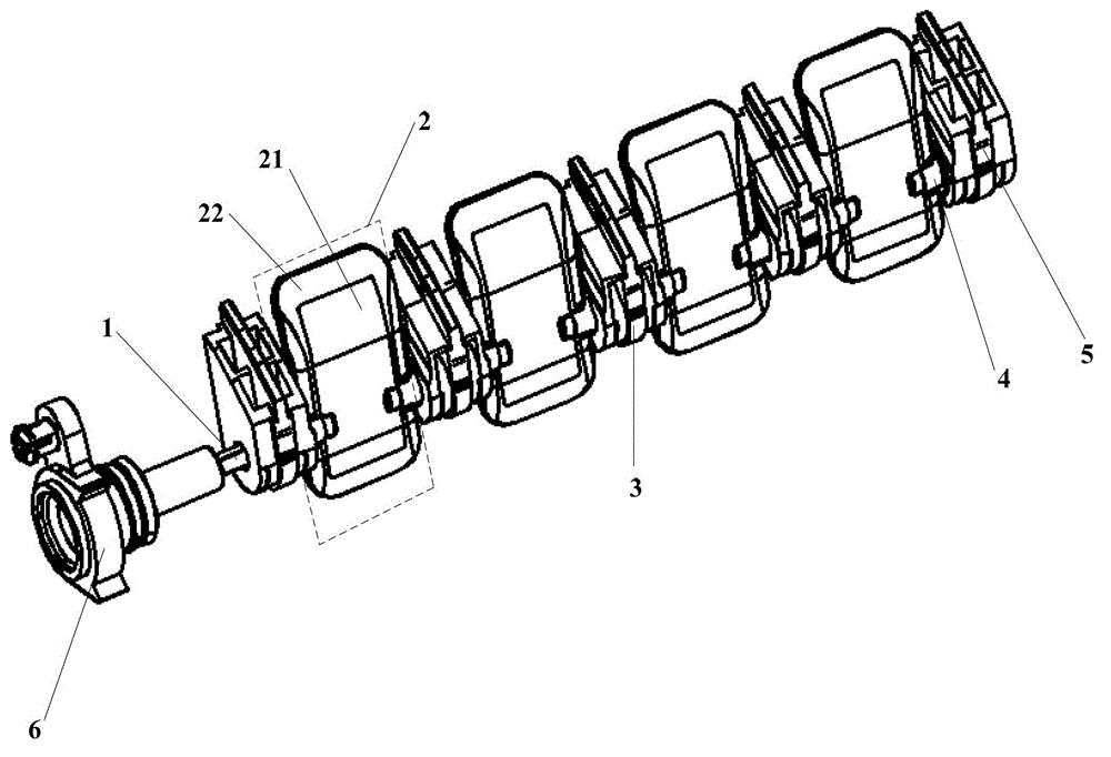
[0046] figure 1 It is a schematic structural diagram of a variable intake manifold system provided in Embodiment 1 of the present application.
[0047] Such as figure 1 As shown, a variable intake manifold system provided by the embodiment of the present application includes: a metal shaft 1, a plurality of valve plates 2 forming an integrated valve plate group, a plurality of split bearing seats 3, two Bearing 4, two independent bearing blocks 5 and swing arm 6. Wherein, the valve sheet 2 includes: a hard rubber substrate 21 and a soft rubber coating 22 .
[0048] Among them: a plurality of valve plates 2 form an integrated valve plate group through plastic overmolding, and the integrated valve plate group formed by multiple valve plates 2 is fixed on the metal shaft 1 through plastic overmolding, and is connected with the metal shaft. 1 becomes an integrated structure; the two-piece bearing seat 3 is arranged between the adjacent valve plates 2; the two bearings 4 are bot...
Embodiment 2
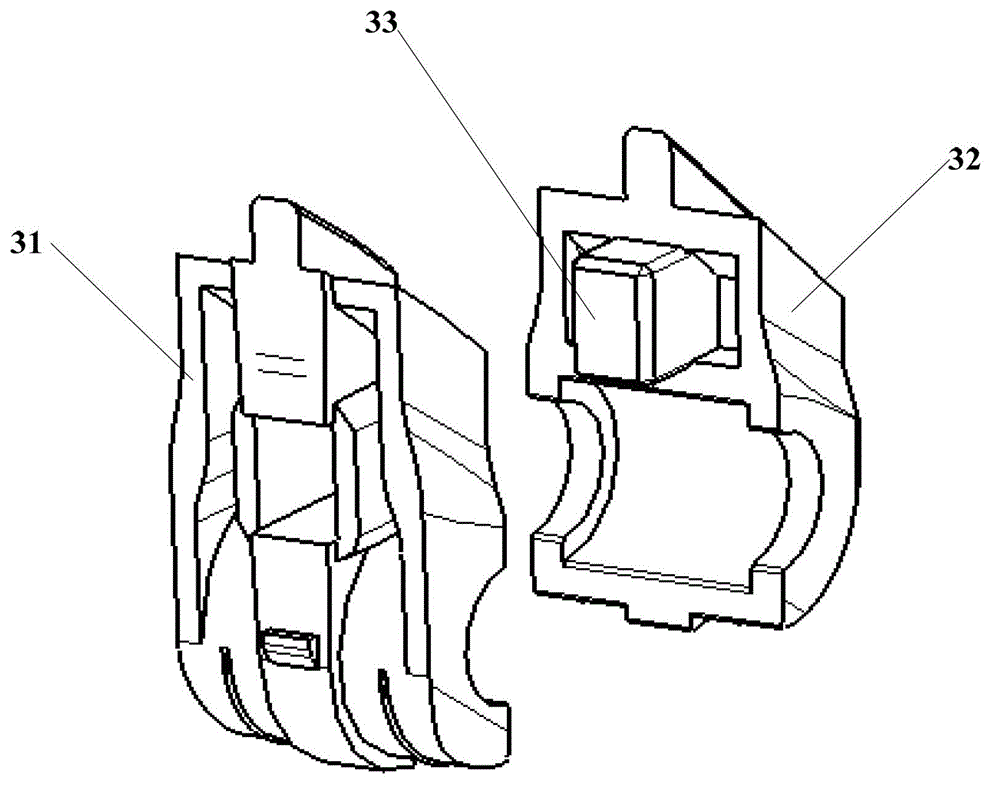
[0059] figure 2 It is a schematic diagram of the detailed structure of the split bearing seat provided in the second embodiment of the present application.
[0060] Such as figure 2 As shown, the structure of the split bearing seat includes: a first half bearing seat 31 , a second half bearing seat 32 and a square positioning structure 33 . Wherein: the first half bearing seat 31 and the second half bearing seat 32 are fixed by the square positioning structure 33 .
[0061] The part connected between the first half bearing seat 31 and the second half bearing seat 32 can be reliably fixed and plugged by the square positioning structure 33, so as to realize the stable positioning between the two half bearing seats, effectively ensuring the split type The shape and position accuracy of the bearing seat. At the same time, due to the simple structure of the split bearing seat, the difficulty in manufacturing and assembly is reduced.
[0062] image 3 It is a partial structur...
Embodiment 3
[0068] Figure 4 It is a schematic structural diagram of the bearing provided in Embodiment 3 of the present application.
[0069] Such as Figure 4 As shown, four semi-cylindrical protrusions 41 and four annular grooves 42 are evenly distributed on the inner ring of the bearing provided in the third embodiment of the present application.
[0070] Figure 5 It is a partial structural schematic diagram of the hard rubber substrate assembled with the bearing provided in Embodiment 3 of the present application.
[0071] Such as Figure 5 As shown, four semi-cylindrical grooves 211 and four annular protrusions 212 are provided on the hard rubber substrate 21 assembled with the bearing provided in the third embodiment of the present application. The four semi-cylindrical grooves 211 are matched with the four semi-cylindrical protrusions 41 provided on the bearing 4 , and the four annular protrusions 212 are matched with the four annular grooves 42 provided on the bearing 4 .
...
PUM
 Abstract
Description
Claims
Application Information