Industrial equipment cooling system and control method thereof

A technology for cooling systems and industrial equipment, applied in coolers, lighting and heating equipment, household refrigeration equipment, etc., can solve the problems of high energy consumption of the system, high operating costs, and increased industrial energy consumption, etc. load, reduce operating costs, and achieve high energy efficiency

Inactive Publication Date: 2013-03-20
安徽日源环保能源科技有限公司
View PDF8 Cites 3 Cited by
  • Summary
  • Abstract
  • Description
  • Claims
  • Application Information

AI Technical Summary

Problems solved by technology

[0003] Industrial cooling has its own characteristics. Generally, cooling equipment is required throughout the year, and a cooling system is required to provide low-temperature cold water throughout the year. Conventionally, there are water-cooled chillers and specially designed air-cooled chillers, etc., but more or less There are the following deficiencies: First, water-cooled or air-cooled chillers produce a large amount of waste heat while providing low-temperature cold water needed for industrial cooling, which is not fully utilized, resulting in low energy utilization and increased industrial energy consumption. Second, the air-cooled chiller uses the cooling capacity of the air to cool down the air-cooled condenser, but this technology is not yet perfect for refrigeration at extremely low temperatures, especially when chilled water is produced below -5°C, the wind The design of cold water chillers is not mature; third, water-cooled or air-cooled chillers are completely used for cooling and cooling, and their system consumes a lot of energy and high operating costs

Method used


Image

  • Industrial equipment cooling system and control method thereof

Examples


Embodiment Construction

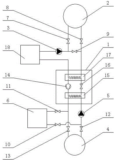
[0028] See figure 1 , a cooling system for industrial equipment, including a water source heat pump 1, a first cooling tower 2, a chilled water circulation pump 3, a second cooling water tower 4, a cooling water circulation pump 5, waste heat utilization equipment 6 and a plurality of control valves, chilled water circulation pump 3 The output end of the first cooling water tower 2 is connected to the input end of the first cooling water tower 2 through the first control valve 7, the output end of the first cooling water tower 2 is connected to the refrigeration heat exchange end of the water source heat pump 1 through the second control valve 8, and the chilled water circulation pump 3 The output end of the output port is connected to the cooling heat exchange end of the water source heat pump 1 through the third control valve 9, the heat exchange end of the waste heat utilization device 6, the fourth control valve 10, the cold water cooling circulation pump 5, and the heating...


PUM


Abstract

The invention discloses an industrial equipment cooling system and a control method thereof. The industrial equipment cooling system comprises a water source heat pump, a cooling water tower, a chilled water circulating pump and a plurality of control valves, wherein an output end of the chilled water circulating pump is connected with an input end of the cooling water tower through a first control valve; the output end of the cooling water tower is connected with a refrigeration and heat transfer end of the water source heat pump through a second control valve; and the output end of the chilled water circulating pump is connected with the refrigeration and heat transfer end of the water source heat pump through a third control valve. Under the condition that the external temperature is low, the cooling water pump is preferably used for reducing temperature of industrial cooling water, the energy consumption is obviously lower than the energy consumption of refrigerating by starting a water chilling unit, the load of starting the water source heat pump is obviously reduced, and the running cost of the cooling system is reduced.

Description

[0001] technical field [0002] The invention relates to the field of industrial equipment cooling, in particular to an industrial equipment cooling system and a control method thereof. Background technique [0003] Industrial cooling has its own characteristics. Generally, cooling equipment is required throughout the year, and a cooling system is required to provide low-temperature cold water throughout the year. Conventionally, there are water-cooled chillers and specially designed air-cooled chillers, etc., but more or less There are the following deficiencies: First, water-cooled or air-cooled chillers produce a large amount of waste heat while providing low-temperature cold water needed for industrial cooling, which is not fully utilized, resulting in low energy utilization and increased industrial energy consumption. Second, the air-cooled chiller uses the cooling capacity of the air to cool down the air-cooled condenser, but this technology is not yet perfect for refr...

Claims


Application Information

Patent Timeline
IPC IPC(8): F25D16/00F25D29/00
Inventor 蒋海洋张明军
Owner 安徽日源环保能源科技有限公司
Why Eureka
Try Eureka