Method of amending phase position collecting error caused by frequency variation in phased rectifier control
A technology of phase-controlled rectification control and frequency change, which is applied in the direction of pulse shaping, measuring electrical variables, measuring devices, etc., can solve the problems of difficult selection of response sensitivity devices, difficult zero-crossing phase errors, and unsatisfactory problems, so as to solve the problem of thyristor replacement The effect of current conduction failure, elimination of zero-crossing error, and easy operation
- Summary
- Abstract
- Description
- Claims
- Application Information
AI Technical Summary
Problems solved by technology
Method used
Image

Examples
Embodiment Construction
[0025] The present invention will be further described in detail below in conjunction with the accompanying drawings and specific embodiments.
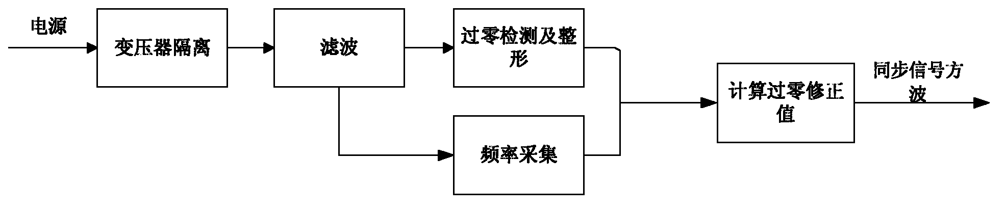
[0026] Such as image 3 As shown, a method for correcting phase acquisition errors caused by frequency changes in the phase-controlled rectification control of the present invention, the steps are:
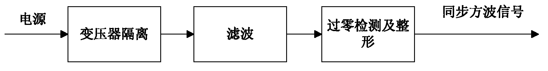
[0027] (1) A synchronous transformer is used to realize power isolation. After the network voltage signal is isolated by a synchronous transformer, the obtained power signal is filtered by a band-pass filter and then subjected to zero-crossing detection and shaping to remove high-order harmonics and DC components;
[0028] (2) For a filter circuit with fixed parameters and forms, its phase shift deviation has a fixed functional relationship with the frequency of the input signal, that is, the deviation value of the phase shift can be fixed according to the frequency of the input signal;
[0029] (3) The real zero-crossing signal can be r...
PUM
 Abstract
Description
Claims
Application Information
 - Generate Ideas
- Intellectual Property
- Life Sciences
- Materials
- Tech Scout
- Unparalleled Data Quality
- Higher Quality Content
- 60% Fewer Hallucinations
Browse by: Latest US Patents, China's latest patents, Technical Efficacy Thesaurus, Application Domain, Technology Topic, Popular Technical Reports.
© 2025 PatSnap. All rights reserved.Legal|Privacy policy|Modern Slavery Act Transparency Statement|Sitemap|About US| Contact US: help@patsnap.com