
LED chip and manufacturing method thereof

A technology of LED chips and manufacturing methods, which is applied to electrical components, circuits, semiconductor devices, etc., and can solve problems such as reducing efficiency

Inactive Publication Date: 2013-03-20
ENRAYTEK OPTOELECTRONICS
View PDF3 Cites 12 Cited by
  • Summary
  • Abstract
  • Description
  • Claims
  • Application Information

AI Technical Summary

Problems solved by technology

Therefore, only a part of the light generated inside the LED chip can be emitted, which greatly reduces the efficiency of the LED.

Method used


Image

  • LED chip and manufacturing method thereof
  • LED chip and manufacturing method thereof
  • LED chip and manufacturing method thereof

Examples


Embodiment Construction

[0033] As mentioned in the background art, improving the luminous efficiency of LED chips is a direction of continuous exploration and improvement in the industry.

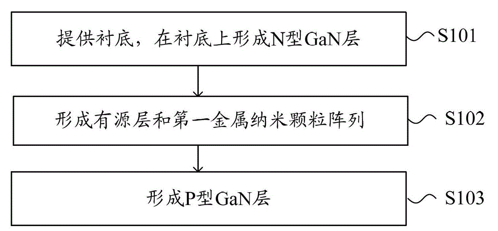
[0034] To this end, the present invention provides an LED chip and a manufacturing method thereof. The LED chip has a first metal nanoparticle array formed on the interface between the active layer and its adjacent layer, which can improve the internal quantum efficiency of the LED, thereby improving the LED chip. luminous efficiency.

[0035] The present invention will be described in more detail below with reference to the accompanying drawings, wherein preferred embodiments of the present invention are shown, it should be understood that those skilled in the art can modify the present invention described herein and still achieve the advantageous effects of the present invention. Therefore, the following description should be understood as the broad knowledge of those skilled in the art, but not as a limitation ...


PUM


Abstract

The invention discloses an LED (light-emitting diode) chip and a manufacturing method of the LED chip. The LED chip is characterized in that a first metal nanoparticle array is formed on an interface between an active layer and an adjacent layer of the active layer. Metal nanoparticles of the first metal nanoparticle array are excited by the light emitted from the active layer and provides an additional quantum well localized state for the active layer, so that the probability that electrons conduct radiationless recombination with voids by a defect level is reduced; an inner quantum effect is improved, and the luminous efficiency of the LED chip is improved.

Description

technical field [0001] The invention relates to the technical field of LED manufacturing, in particular to an LED chip and a manufacturing method thereof. Background technique [0002] Light Emitting Diode (LED, Light Emitting Diode) is a semiconductor solid-state light-emitting device that uses a semiconductor PN junction as a light-emitting material to convert electricity into light. When a forward voltage is applied to both ends of the semiconductor PN junction, the electrons and holes injected into the PN junction recombine, and the excess energy is released in the form of photons. LED has the advantages of long life and low power consumption. With the maturity of technology, the application fields of LED are becoming more and more diversified, and the requirements for the power and brightness of LED chips are also getting higher and higher. How to increase the power of LED chips It is one of the problems encountered in the development of LED. The power of the LED is c...

Claims


Application Information

Patent Timeline
IPC IPC(8): H01L33/02H01L33/00
Inventor 毕少强
Owner ENRAYTEK OPTOELECTRONICS
Learn More