Reflective array face and reflective array antenna

A reflective array antenna and reflective array technology, which is applied to antennas, antenna arrays, antennas suitable for movable objects, etc., can solve problems such as reflective array work, and achieve the effects of automation, strong versatility, and easy automation

Active Publication Date: 2013-03-20
KUANG CHI INNOVATIVE TECH +1
View PDF4 Cites 31 Cited by
  • Summary
  • Abstract
  • Description
  • Claims
  • Application Information

AI Technical Summary

Problems solved by technology

[0005] The technical problem to be solved by the present invention is to provide a reflective surface capable of receiving electromagnetic waves incident i

Method used


Image

  • Reflective array face and reflective array antenna
  • Reflective array face and reflective array antenna
  • Reflective array face and reflective array antenna

Examples


no. 1 example

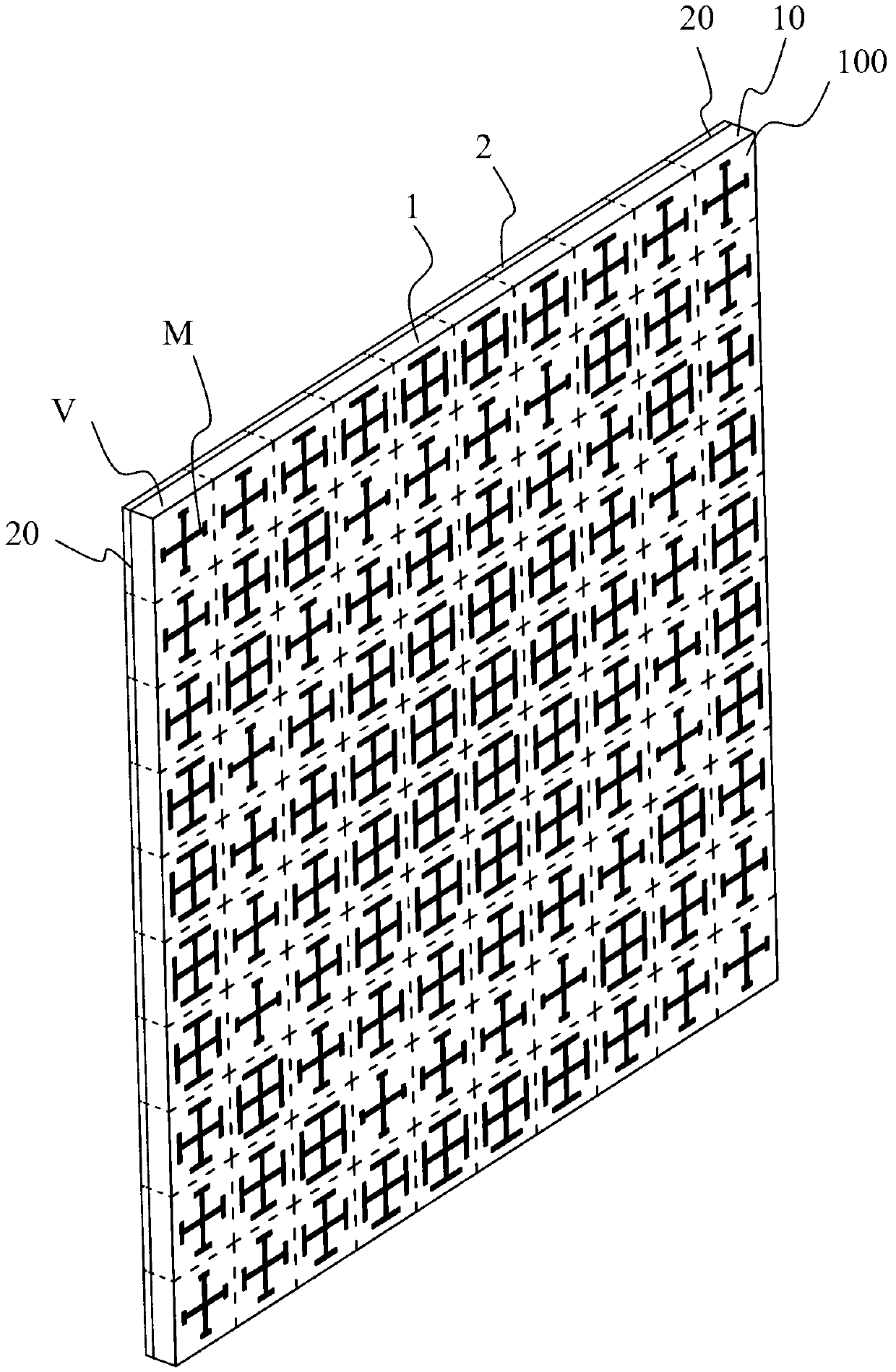
[0195] The included angle α between the electromagnetic wave transmitted by the satellite received by the reflecting front and the normal direction of the reflecting front is 45 degrees, and the included angle α is hereinafter referred to as the deflection angle. The reflective front is a circular thin plate with a diameter of 500mm, on which there are Figure 5 Man-made structural unit shown. Such as Figure 18 As shown, it is the far-field diagram of the reflectarray antenna with a deflection angle of 45 degrees as the transmitting antenna. It can be seen that its main beam is directed at 45 degrees. Focus on source.

[0196] After actual testing, the performance of the antenna remains good when the defocus angle is within the range of 30-50 degrees, and there are still signals beyond this range, but the signal quality is not high. That is, in this embodiment, the reflective array has the ability to focus incident electromagnetic waves that form an angle range of 30-50 de...

no. 2 example

[0224] The deflection angle α of the antenna is 50 degrees. The reflective front is a circular thin plate with a diameter of 500mm, on which there are Figure 5 Man-made structural unit shown. Such as Figure 19 As shown, it is the far-field diagram of the reflectarray antenna with a deflection angle of 50 degrees. It can be seen that its main beam is directed at 50 degrees. Focus on source.

[0225] After actual testing, the performance of the antenna is still good when the defocus angle is within the range of 35-55 degrees, and there are still signals beyond this range, but the signal quality is not high. That is to say, in this embodiment, the reflective array has the ability to focus incident electromagnetic waves that form an angle range of 35-55 degrees with respect to the normal direction of the reflective array.

[0226] According to different application occasions, the satellite receiving antenna of the second embodiment can have three working environments, that i...

no. 3 example

[0231] The deflection angle α of the antenna is 65 degrees. The reflective front is a circular thin plate with a diameter of 500mm, on which there are Figure 5 Man-made structural unit shown. Such as Figure 20 As shown, it is the far-field diagram of the reflectarray antenna with a deflection angle of 65 degrees. It can be seen that its main beam is directed at 65 degrees. Focus on source.

[0232] After actual testing, the performance of the antenna remains good when the defocus angle is within the range of 50-70 degrees, and there are still signals beyond this range, but the signal quality is not high. That is to say, in this embodiment, the reflective array has the ability to focus incident electromagnetic waves that form an angle range of 50-70 degrees with respect to the normal direction of the reflective array.

[0233] According to different application occasions, the satellite receiving antenna of the third embodiment can have three working environments, that is,...


PUM

PropertyMeasurementUnit
Widthaaaaaaaaaa
Diameteraaaaaaaaaa

Abstract

The invention provides a reflective array antenna. The reflective array antenna comprises a reflective array face, and the reflective array face comprises a function board which is used for beam modulating of incidence electromagnetic wave and a reflecting layer which is arranged on one side of the function board and is used for reflecting the electromagnetic wave. The function board comprises two or more function board units. The reflecting layer comprises reflecting units, wherein, the number of the reflecting units corresponds to the number of the function board units. A phase shift unit which is used for shifting phase is formed by each function board unit and each corresponding reflecting unit. The reflective array face has a focusing ability for the incidence electromagnetic wave in a scheduled angle range with a normal direction of the reflective array face. According to the fact that the reflective array antenna has the focusing ability of the incidence electromagnetic wave in the preset angle range, the reflective array antenna is capable of having a plurality of focal points so as to be used for different environment or areas.

Description

technical field [0001] The invention relates to the communication field, and more specifically, to a reflection front and a reflection array antenna. Background technique [0002] Existing reflectarray antenna The most common reflective focusing antenna in the prior art is a parabolic antenna. The spherical wave radiated by the feed source placed on the focus of the paraboloid becomes a plane wave parallel to the axis of the antenna after being reflected by the paraboloid, so that the antenna plane The field distribution on the aperture is the same phase field. The parabolic antenna has the advantages of simple structure, high gain, strong directivity, and wide operating frequency band. However, the curved parabolic reflector not only makes the antenna bulky and heavy, but also limits its application in places with limited space, such as spacecraft antennas. In addition, the parabolic antenna relies on the beam scanning method of mechanical rotation, which is difficult to m...

Claims


Application Information

Patent Timeline
IPC IPC(8): H01Q15/14H01Q19/10H01Q21/00H01Q3/16H01Q1/27
Inventor 刘若鹏季春霖李星昆殷俊
Owner KUANG CHI INNOVATIVE TECH
Why Eureka
Try Eureka