Initial positioning method for permanent-magnet synchronous motor

A permanent magnet synchronous motor, initial positioning technology, applied in the direction of control generator, motor generator control, electronic commutation motor control, etc., to achieve the effect of simple hardware structure and convenient operation

Inactive Publication Date: 2013-03-20
WISDRI WUHAN AUTOMATION
View PDF4 Cites 21 Cited by
  • Summary
  • Abstract
  • Description
  • Claims
  • Application Information

AI Technical Summary

Problems solved by technology

The disadvantage of this method is that the controller must identify th

Method used


Image

  • Initial positioning method for permanent-magnet synchronous motor
  • Initial positioning method for permanent-magnet synchronous motor
  • Initial positioning method for permanent-magnet synchronous motor

Examples


Embodiment Construction

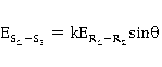
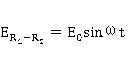
[0021] figure 1 For the working principle diagram of the resolver, the primary excitation winding of the resolver (R 1 -R 2 ) and two-phase quadrature secondary pole induction winding (S 1 -S 3 is the first secondary induction winding, S 2 -S 4 For the second secondary induction winding) on ​​the stator side. On the rotor side are the winding coils that are flux coupled to the primary and secondary windings. When the resolver rotor rotates synchronously with the motor, an AC excitation voltage is applied to the primary excitation winding, and an induced electromotive force will be generated in the secondary output winding, which is the product of the excitation and the sine and cosine of the rotor rotation angle. The input and output relationship of the resolver is as follows:

[0022] (1),

[0023] (2),

[0024] (3),

[0025] In the formula: - the maximum amplitude of the excitation...


PUM


Abstract

The invention provides an initial positioning method for a permanent-magnet synchronous motor. The method includes that a rotary transformer, a rotation-digit conversion module and a level conversion module are additionally arranged, wherein a stator winding and a rotor winding of the rotary transformer are respectively fixed on a stator and a rotor of the permanent-magnet synchronous motor, the stator winding comprises a primary winding and a secondary winding, the rotation-digit conversion module provides exciter signals for the primary winding and converts envelop signals output by the secondary winding into absolute angle signals, the rotation-digit conversion module communicates with a main processor of a system through the level conversion module, when the system is powered on initially, the rotor stops in the position of an angle of 0 degree, and the main processor acquires the initial angle A0 of the motor, then the permanent-magnet synchronous motor runs in a closed-loop vector mode, the main processor acquires an absolute angle Ax of the motor, and the position angle of the rotor of the permanent-magnet synchronous motor satisfies the equation that theta=Ax-A0, every time the system is powered off, the current position angle of the rotor is stored, and when the system is powered on again, the current position angle of the motor is taken as an initial angle.

Description

technical field [0001] The invention relates to a frequency conversion speed regulation system, in particular to an initial positioning method for a permanent magnet synchronous motor based on a resolver. Background technique [0002] When performing servo control on the permanent magnet synchronous motor, the controller controls the vector direction of the stator three-phase current synthetic magnetic field. In order to effectively control the stator magnetic field vector, accurate measurement of the rotor position is required. Usually the most economical and effective method is to install an incremental encoder on the rotor of the motor, and use the number of pulses output by the encoder to represent the change of the rotor position. In this method, the controller needs to know the initial position of the rotor first, and then determine the direction of rotation of the rotor and the angle it has turned according to the AB pulse sent by the encoder. When the system is fir...

Claims


Application Information

Patent Timeline
IPC IPC(8): H02P21/00H02P21/32
Inventor 徐晖王胜勇卢家斌王国强唐文秀王傲能
Owner WISDRI WUHAN AUTOMATION
Why Eureka
Try Eureka