
Improved combustion engine

一种发动机、内燃机的技术,应用在往复活塞发动机领域,能够解决活塞行程短、吸入空气进入燃烧室的时间短等问题,达到不浪费能量的效果

Inactive Publication Date: 2013-03-20
EXODUS R&D INT PTE
View PDF4 Cites 2 Cited by
  • Summary
  • Abstract
  • Description
  • Claims
  • Application Information

AI Technical Summary

Problems solved by technology

The use of a traditional scotch yoke is often not always feasible due to the short stroke of the piston and the very short time available to draw air into the combustion chamber

Method used


Image

  • Improved combustion engine
  • Improved combustion engine
  • Improved combustion engine

Examples


Embodiment Construction

[0053] The present invention will be described in detail below in conjunction with the accompanying drawings. While representative embodiments are included in the following description, other embodiments are not excluded, and changes may be made in the described embodiments without departing from the spirit and scope of the invention. Throughout the embodiments and the following description, the same reference numerals will be used to designate the same or similar parts, if possible.

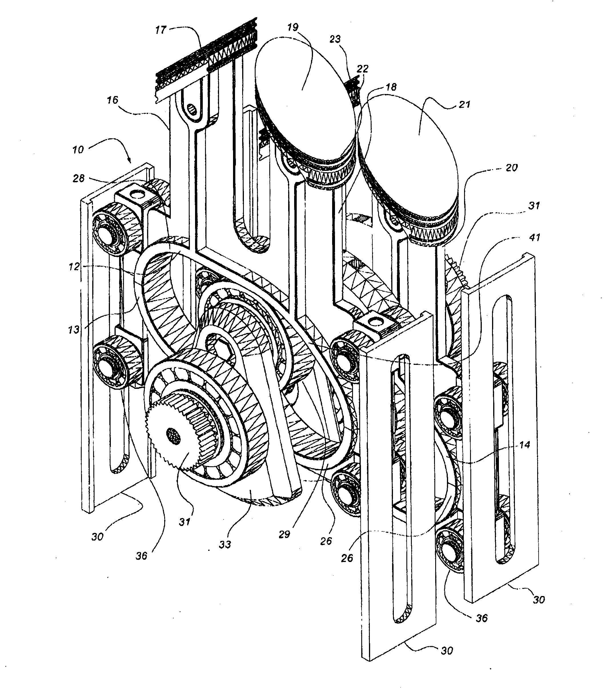
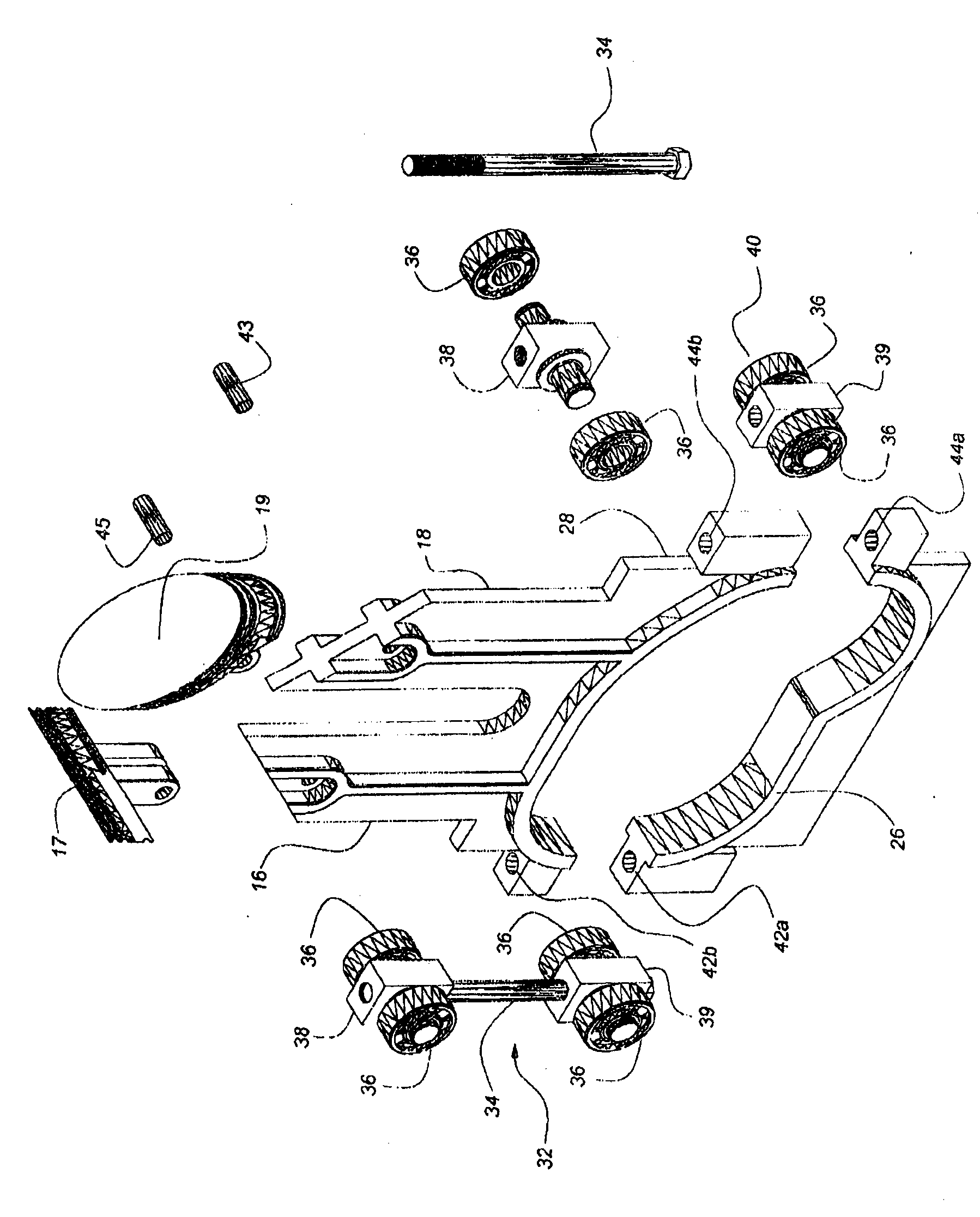
[0054] Referring now to the more detailed drawings, the internal combustion engine 10 includes as part of its arrangement a scotch yoke structure 12 divided into a top 28 and a bottom 26 .

[0055] The Scotch yoke structure 12 includes an inner peripheral edge 13 which provides a guide suitable for rotation of the wheel member 29 about thereabout.

[0056] figure 1 , a four-piston, or more precisely, four-cylinder internal combustion engine is shown.

[0057] For clarity, the existing cylinde...


PUM


Abstract

The present invention relates to internal combustion engines and more particularly reciprocating piston engines utilising Scotch yokes to translate rectilinear movement to rotary motion. In particular, the piston and / or pistons of the engine of the present invention can be placed in their topmost position for a period of time for the effective ignition and combustion of the air / fuel mixture for a given fuel charge, hence therefore providing an increased efficiency of the piston engine with a more efficient coupling between the piston and / or the power shaft driving the crank.

Description

technical field [0001] This invention relates to internal combustion engines and in particular to reciprocating piston engines utilizing a Scotch yoke to convert linear motion to rotary motion. Background technique [0002] Those skilled in the art will appreciate that the internal combustion engine has been with us for decades now and has become the most familiar design in which a reciprocating piston uses a connecting rod connecting the piston to a crank pin on the crankshaft to translate the linear reciprocating motion of the piston into the crank The rotational movement of the axis. [0003] Typically, a connecting rod is connectable where its ends connect to the piston and crankpin. This piston is connected to the connecting rod by a toggle pin passing through the piston and connecting rod. These designs of such internal combustion engines are generally referred to as slider crank engines. However, time has shown that these types of internal combustion engines have s...

Claims


Application Information

Patent Timeline
Patent Type & Authority Applications(China)
IPC IPC(8): F01B9/02F02B75/32F16H21/36
CPCF01B9/023
Inventor 乔治·弗朗什
Owner EXODUS R&D INT PTE
Learn More