Eureka AIR delivers breakthrough ideas for toughest innovation challenges, trusted by R&D personnel around the world.

Framework assembly sieve basket of horizontal vibrating centrifuge

A technology of vibrating centrifuge and combination body, applied in directions such as centrifuges, can solve the problems of increasing production cost, affecting filtration efficiency, complicated structure, etc., and achieving the effects of convenient production, improved production efficiency and reduced production cost

Inactive Publication Date: 2013-03-27
JINGJIN ENVIRONMENTAL PROTECTION INC
View PDF4 Cites 0 Cited by
  • Summary
  • Abstract
  • Description
  • Claims
  • Application Information

AI Technical Summary

Problems solved by technology

[0002] The sieve basket is the main filter element of the horizontal vibrating centrifuge. The filtered material enters the inner cavity of the sieve basket through the upper feeding hole of the centrifuge. The filter cake is released from the gap of the screen mesh by centrifugal force and enters the water tank body, and then discharged from the drain hole at the lower part of the water tank body. The separated filter cake is released from the inner cavity of the screen basket by the vibration of the centrifuge and enters the discharge hole to realize the separation of solid materials and liquids. The horizontal vibrating centrifuge is the equipment for continuous filtration operation. The design structure of the screen basket is very important. The structure of the currently used screen basket is double-layer, which is cumbersome and troublesome to manufacture. It often deforms after continuous high-speed rotation and vibration filtration operations. and damage, resulting in frequent replacement of the sieve basket, increasing production costs and affecting filtration efficiency, which is the shortcoming of the sieve basket of the current horizontal vibrating centrifuge

Method used


Image

  • Framework assembly sieve basket of horizontal vibrating centrifuge

Examples


Embodiment Construction

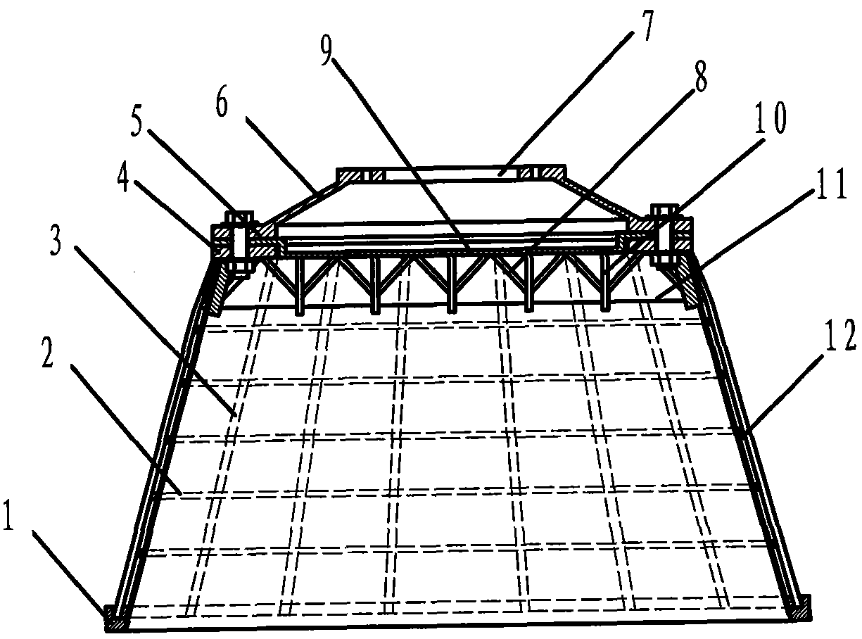
[0011] see figure 1 As shown, the present invention provides a screen basket of a skeleton assembly of a horizontal vibrating centrifuge. It can be seen from the schematic diagram that the shape of the technical scheme is a conical skeleton assembly screen basket, and upper flanges 4 and lower flanges are arranged at both ends. Lan 1 is connected with rib bar 3 and screen ring bar 2 to form a skeleton combined screen basket. The upper flange 4 and the lower flange are cut by gas-cutting medium plate steel, and the material is carbon structural steel. Make the mold of the inner diameter body of the sieve basket assembly, place the screen ring bar 2 in the mold for clamping and positioning, arrange the upper flange 4, the lower flange 1 and the ribs 3 in the mold for clamping and positioning, first place the Corner spot welding and then symmetrical welding, the welded sieve ring bar 2 contact points are uniform and then welded firmly, after the welding is completed, the mold is ...


PUM


Abstract

The invention relates to a framework assembly sieve basket of a horizontal vibrating centrifuge. The technical scheme of the invention is as follows: the framework assembly sieve basket is conical, an upper flange and a lower flange are arranged on two ends of a sieve basket, the upper flange and the lower flange are connected by ribs and sieve loops to form the framework assembly sieve basket, the upper flange is provided with a strength plate which is connected with the ribs, the strength plate is provided with reinforcing ribs and splayed inclined ribs which are connected with the ribs, the upper flange is provided with a convex baffle plate which is connected with an external flange of a support tray, a sieve screen is arranged on the sieve loops at the inner side of the sieve basket, the support tray is arranged on the sieve basket, the external flange of the support tray is connected with the upper flange of the sieve basket, and an internal flange of the support tray is connected with a flange of a mainshaft. The framework assembly sieve basket is uniform in structure stress, high in strength, stable to operate in a high-speed centrifugal rotating and filtering process and improved in production efficiency.

Description

technical field [0001] The invention relates to a centrifuge screen basket. In more detail, it relates to a screen basket of a skeleton assembly of a horizontal vibrating centrifuge. Background technique [0002] The sieve basket is the main filter element of the horizontal vibrating centrifuge. The filtered material enters the inner cavity of the sieve basket through the upper feeding hole of the centrifuge. The filter cake is released from the gap of the screen mesh by centrifugal force and enters the water tank body, and then discharged from the drain hole at the lower part of the water tank body. The separated filter cake is released from the inner cavity of the screen basket by the vibration of the centrifuge and enters the discharge hole to realize the separation of solid materials and liquids. The horizontal vibrating centrifuge is the equipment for continuous filtration operation. The design structure of the screen basket is very important. The structure of the curr...

Claims


Application Information

Patent Timeline
Patent Type & Authority Applications(China)
IPC IPC(8): B04B7/16
CPCB04B7/18
Inventor 姜桂廷杨名杰荣立峰
Owner JINGJIN ENVIRONMENTAL PROTECTION INC
Why Eureka
Eureka Blog
Learn More