pneumatic tire

A pneumatic tire, tire circumferential technology, applied to tire parts, tire tread/tread pattern, transportation and packaging, etc., can solve the problems of reduced handling stability and easy reduction of rigidity on dry roads, and prevent excessive rigidity Reduce, improve driving performance, suppress the effect of mutual crossing

Active Publication Date: 2016-02-24
SUMITOMO RUBBER IND LTD
View PDF8 Cites 0 Cited by
  • Summary
  • Abstract
  • Description
  • Claims
  • Application Information

AI Technical Summary

Problems solved by technology

[0005] However, in the above-mentioned pneumatic tire, there is a problem that the rigidity of the land portion tends to be lowered due to the plurality of sipes, and the steering stability on a dry road surface is lowered.

Method used


Image

  • pneumatic tire
  • pneumatic tire
  • pneumatic tire

Examples


Embodiment

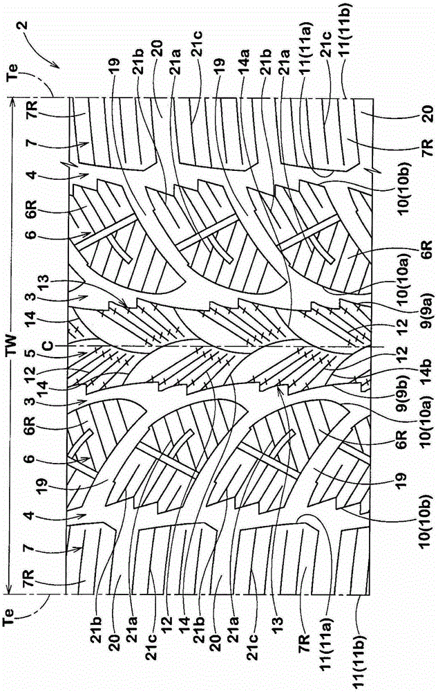
[0060] Based on the specifications in Table 1 a prototype was formed as figure 1 The pneumatic tires with the basic structure and the size of 225 / 65 / R17 were tested, and the braking performance on ice and the handling stability performance on dry roads of each tire were tested. The test method is as follows.

[0061]

[0062] Install each test tire on a 17×7.0J rim, and then install it on all the wheels of a 2000cc vehicle under the condition of an internal pressure of 200kPa, and drive straight on the ice road test route at a speed of 40km / h While applying full brakes, the distance until the vehicle comes to a stop is measured. The results are expressed by an index with the reciprocal of the value of the stopping distance of the tire of Comparative Example 1 (conventional art) as 100, and the larger the numerical value, the better.

[0063]

[0064] Under the same conditions as described above, on a dry asphalt road test course, handlebar responsiveness, rigidity, chara...


PUM


Abstract

The pneumatic tire of the present invention can maintain the handling stability on the dry road and improve the driving performance on the ice and snow road. The pneumatic tire is provided with a plurality of crown circumferential grooves (3) extending continuously along the tire circumferential direction on the tread portion (2), thereby forming a crown land portion ( 5). The crown land portion (5) has a land portion edge (9) along the circumferential groove of the crown land portion (5). A plurality of sipe groups (13) are arranged along the tire circumferential direction, and the sipe group 13 includes a land part edge (9a) from one side inclined in the same direction at an angle of 10° to 80° relative to the tire axial direction. And extend, and form more than three sipe patterns (12) at the terminal end in the crown land portion (5). The angle (θ1) of the sipe group (13) gradually increases from the sipe (12s) arranged on one side in the tire circumferential direction to the sipe (12t) arranged on the other side, and the sipe ( 12) is close to the land portion edge (9b) on the other side of the land portion.

Description

technical field [0001] The present invention relates to a pneumatic tire capable of maintaining steering stability on dry roads and improving running performance on icy and snowy roads. Background technique [0002] Conventionally, in order to improve running performance on icy and snowy roads, there is known a pneumatic tire in which edge components are increased by providing sipes extending parallel to each other in the land portion of the tread portion. As related technologies, there are the following Patent Documents 1 and 2. [0003] Patent Document 1: Japanese Patent Laid-Open No. 2006-51891 [0004] Patent Document 2: Japanese Patent Laid-Open No. 2006-160107 [0005] However, in such a pneumatic tire as described above, there is a problem that the rigidity of the land portion tends to decrease due to the plurality of sipes, and furthermore, the steering stability on a dry road surface decreases. Contents of the invention [0006] The present invention has been m...

Claims


Application Information

Patent Timeline
Patent Type & Authority Patents(China)
IPC IPC(8): B60C11/03B60C11/12
CPCB60C11/1236B60C11/04B60C11/12
Inventor 西胁隆志
Owner SUMITOMO RUBBER IND LTD
Why Eureka
Try Eureka