Underwater concrete spouting laitance prevention water-proof device

An underwater concrete and anti-floating technology, which is applied in construction, infrastructure engineering, etc., can solve problems such as insufficient concrete strength, influence on concrete thickness, and concrete strength, and achieve the effects of shortening the construction period, simple construction, and ensuring concrete strength

Inactive Publication Date: 2013-03-27
GUANGXI CONSTR ENG GROUP THE THIRD CONSTR ENG +1
View PDF10 Cites 7 Cited by
  • Summary
  • Abstract
  • Description
  • Claims
  • Application Information

AI Technical Summary

Problems solved by technology

[0003] The above-mentioned prior art has the following deficiencies: 1. Since the underwater concrete pouring is to squeeze the concrete from bottom to top through the pouring conduit, there is an interface where the concrete pouring surface is in close contact with the water. With the pouring of concrete, the water slowly Infiltration into the concrete will affect the strength of the concrete at the interface. The longer the time, the greater the thickness of the affected concrete part. This is one of the reasons why the concrete strength of the common underwater cast-in-place pile core-pulling inspection is lower than that of the test block; 2. Due to water The pouring concrete pouring surface is soaked in water for a long time, resulting in insufficient concrete strength at the top of the pile
According to national regulations, it is advisable to overfill by 0.8~1m, and then chisel off the overfilling part to ensure the strength of the pile deep concrete. 1m; 3. Due to the need to chisel off the unqualified concrete at the top of the pile (referred to as: broken pile head), it will cause waste of concrete, increase labor costs, and prolong the construction period

Method used


Image

  • Underwater concrete spouting laitance prevention water-proof device
  • Underwater concrete spouting laitance prevention water-proof device
  • Underwater concrete spouting laitance prevention water-proof device

Examples


Embodiment Construction

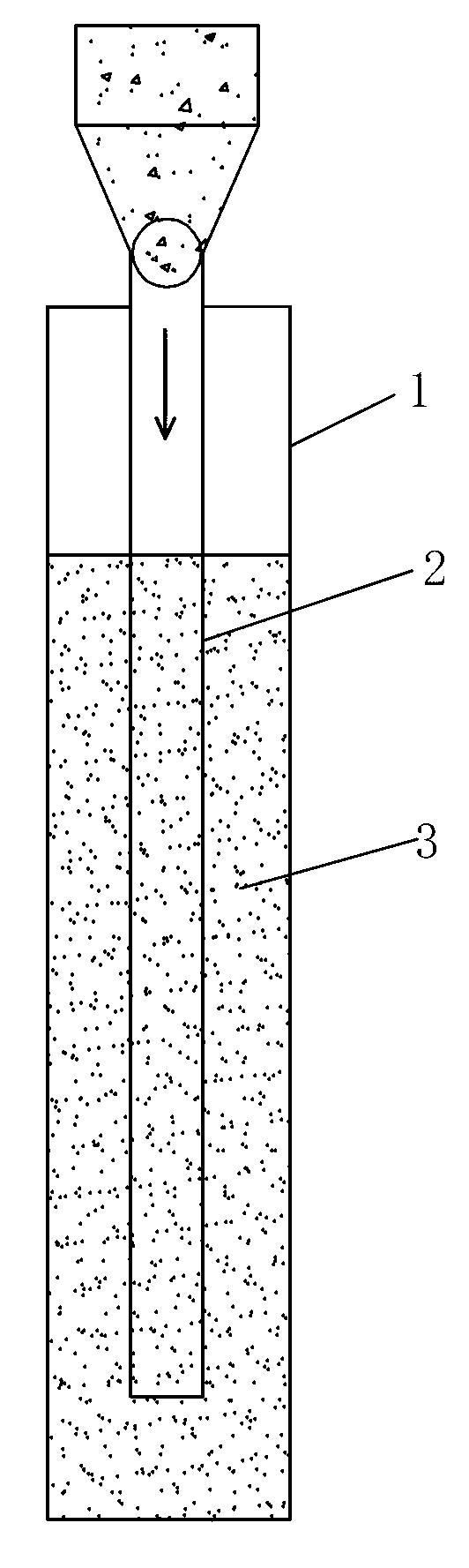
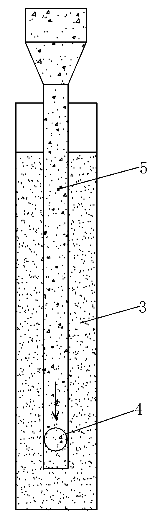
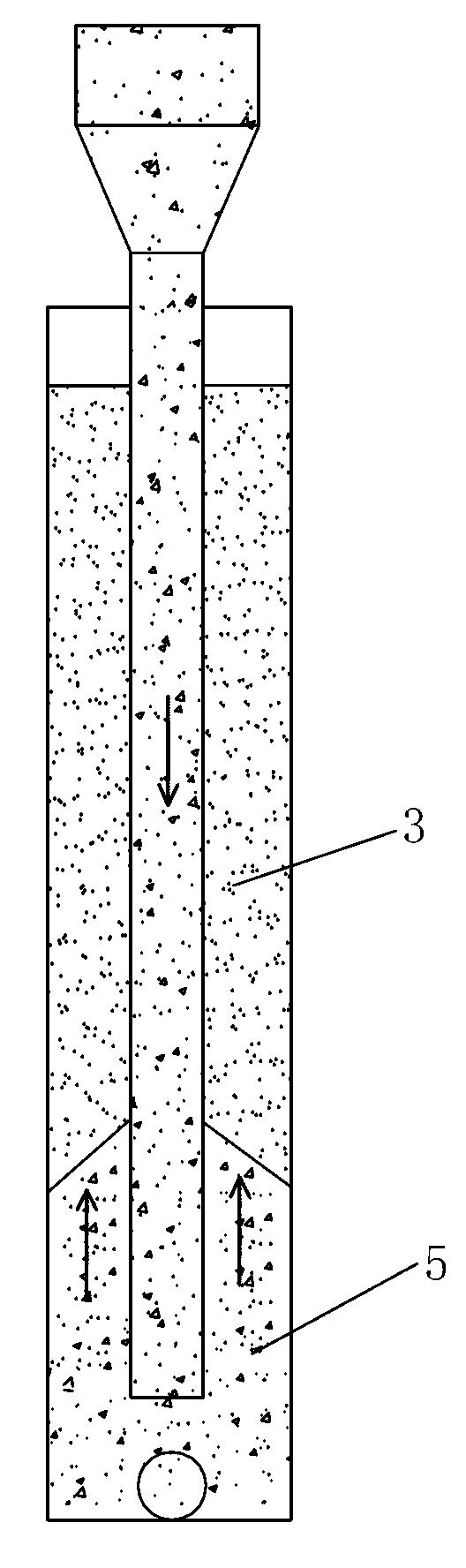
[0029] Such as Figure 5 to Figure 9 As shown, the underwater concrete pouring anti-floating slurry water-retaining device of the present invention includes an annular water-repelling plate, a rubber barrier ring, an elastic brush 15 and an air bag, and the annular water-repelling plate is arranged on the pouring conduit 2 outside and the inner wall of the reinforcement cage (not shown in the figure) in the pile body 1, the rubber barrier ring is arranged on the inner side of the inner ring of the annular water baffle and sleeved on the outer wall of the pouring conduit 2, and the elastic brush 15 is uniform Connected to the outer circumference of the annular water baffle and extend from the outer circumference of the annular water baffle to the outer wall of the pile body 1, the elastic brush 15 is made of hard plastic, the outer edge of the annular water baffle is connected with a side rib 14, and the elastic brush 15 evenly connected to the side ribs 14. The air bag is con...


PUM


Abstract

The invention relates to an underwater concrete spouting laitance prevention water-proof device, which relates to the field of building engineering. The spouting laitance prevention water-proof device comprises an annular water-proof board, a rubber barrier ring, an elastic hair brush and an air chamber; the annular water-proof board is arranged between the outer side of a spouting guide tube and the inner wall of a steel reinforcement cage inside a pile body; the rubber barrier ring is arranged inside the inner ring of the annular water-proof board and sleeved on the outer wall of the spouting guide tube; the elastic hair brush is uniformly connected with the outer circumference of the annular water-proof board and is extended to the outer wall of the pile body from the outer circumference of the annular water-proof board; the air chamber is connected with the upper side of the annular water-proof board; and the air chamber is connected with an inflating guide tube. The underwater concrete spouting laitance prevention water-proof device disclosed by the invention can be submerged underwater successfully, and also can be tightly attached to the concrete spouting surface, so that the concrete spouting surface is isolated from water, the concrete strength of pile head is efficiently ensured, and the device is simple in construction, convenient to operate, low in cost and short in time limit for a project.

Description

technical field [0001] The invention relates to the field of construction engineering, in particular to an anti-floating slurry water-repellent device used in underwater pouring. Background technique [0002] At present, the pouring method of underwater concrete is: after the reinforcement cage (not shown in the figure) in the pile body is installed, the pouring conduit (such as figure 1 shown), the distance between the bottom of the perfusion conduit and the bottom of the hole is 300-500mm. figure 2 shown). There must be enough concrete reserves for pouring concrete, and the pouring conduit should not be less than 0.8m buried in the concrete pouring surface at one time. When pouring concrete, control the depth of the pouring conduit buried in the concrete to 2-6m, and do not allow the pouring conduit to lift out of the concrete pouring surface. The principle of this method: the concrete mixture enters under the initial poured concrete through the sealingly connected pou...

Claims


Application Information

Patent Timeline
Patent Type & Authority Applications(China)
IPC IPC(8): E02D15/06
Inventor 周志荣梁德初黄澎赖溯欣李成宏朱红年胡滨
Owner GUANGXI CONSTR ENG GROUP THE THIRD CONSTR ENG
Why Eureka
Try Eureka