
A vehicle-mounted mud pump unit device

A mud pump and unit technology, which is applied in the field of vehicle-mounted mud pump unit installation, can solve the problems of large space occupation, mud failure, broken frame, etc., and achieves the effect of solving large space occupation, easy arrangement and ensuring stability.

Active Publication Date: 2016-05-11
山东恒利矿场设备有限公司
View PDF6 Cites 0 Cited by
  • Summary
  • Abstract
  • Description
  • Claims
  • Application Information

AI Technical Summary

Problems solved by technology

The drilling pump unit is placed on a large base as a whole, and it needs to be lifted by a crane when it is transported. At the same time, a transport vehicle and tools are needed, which is time-consuming and laborious.
After improvement, someone proposed a technical solution in which the base is fixed on the frame, and the support legs of the oil cylinder on the frame are positioned and fixed. However, due to the high power of the drilling mud pump unit, which exceeds 800-2200 horsepower, the equipment The weight is also huge. During the operation of the mud pump, due to vibration, ground tilt and other reasons, there are often failures such as bending, breaking or even tearing the frame of the oil cylinder, which greatly affect the normal operation of the drilling pump.
Generally, most of the oil drilling and exploration equipment work in relatively remote fields, and the equipment cannot be transported in time after a problem occurs, which brings a lot of trouble to the repair
The F series pump is especially used, because the mud discharge four-way and the discharge filter are respectively located on both sides of the mud pump, which takes up a lot of space, increases the volume of the unit, and also brings inconvenience to transportation.
The safety valve of the mud pump does not work normally, and the mud in the lower pipeline does not flow to form a dead zone, and solid particles are easy to settle on the lower pipe wall, and it is easy to freeze in winter, causing the mud to fail
In addition, due to the lack of heat preservation measures, in cold areas, the equipment is prone to problems such as: water in the pipeline freezes, diesel oil temperature is too low, etc., causing the mud pump and diesel engine to fail to start normally

Method used


Image

  • A vehicle-mounted mud pump unit device
  • A vehicle-mounted mud pump unit device
  • A vehicle-mounted mud pump unit device

Examples


Embodiment Construction

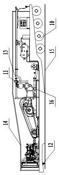
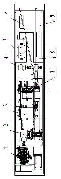
[0010] The structure and use of the present invention will be described in detail below in conjunction with the embodiments given in the accompanying drawings. Referring to the accompanying drawings, this vehicle-mounted mud pump unit device mainly includes a diesel engine, a clutch, a mud pump, a filling pump, an air compressor, and a control cabinet, and is characterized in that the diesel engine (1), the clutch (2), the mud pump (3) , the perfusion pump (4), the air compressor (5) and the control cabinet (6) are installed on the upper surface of the frame (9). The upper surface of the frame is basically a step-shaped surface composed of two plane transition connections. The lower surface is a structure with a front sloped surface and a middle flat surface in contact with the ground, which is connected to a larger sloped surface of a wheel set on which the axle is installed via one end sloped surface and a transition surface. There is a traction shaft (12) below.

[0011] A...


PUM


Abstract

The invention discloses a trailer slush pump unit device. The trailer slush pump unit device mainly comprises a diesel engine, a clutch, a slush pump, a filling pump, an air compressor and a control cabinet and is characterized in that the diesel engine, the clutch, the slush pump, the filling pump, the air compressor and the control cabinet are installed on the upper surface of a rack, the upper surface of the rack is basically the step-shaped surface which is formed by two planes in a way of transition connection, the lower surface of the rack is in a structure that five surfaces which are the inclined surface at the front section, the flat surface with the middle part contacted with the ground, the surface with one inclined end, the transition surface and the large inclined surface of a wheel set provided with a trailer bridge are connected to form a whole body, the inclined surface and the flat surface are connected with the large inclined surface through the surface with one inclined end and the transition surface, and a traction shaft is arranged at the lower side of the surface at the front section. The trailer slush pump unit device has the advantanges that a special trailer chassis is innovatively designed to replace a large chassis of the traditional slush pump unit, so transportation can be facilitated, the special trailer chassis can also be flatly arranged on the ground when the slush pump unit works, and the stability of running of the slush pump unit is ensured; and a traction pin is arranged on the chassis, so that equipment can be transported after the chassis is connected with a trailer head.

Description

technical field [0001] The invention belongs to a drilling mud pump unit in the technical field of petroleum exploration and drilling equipment, and in particular relates to a vehicle-mounted mud pump unit device. Background technique [0002] The existing mud pump unit generally has several major components such as a diesel engine component, a clutch component, a mud pump component, a filling pump component, an air compressor component, and a control cabinet component. The drilling pump unit is placed on a large base as a whole, and it needs to be lifted by a crane when it is transported. At the same time, a transport vehicle and tools are needed, which is time-consuming and laborious. After improvement, someone proposed a technical solution in which the base is fixed on the frame, and the support legs of the oil cylinder on the frame are positioned and fixed. However, due to the high power of the drilling mud pump unit, which exceeds 800-2200 horsepower, the equipment The...

Claims


Application Information

Patent Timeline
Patent Type & Authority Patents(China)
IPC IPC(8): E21B21/00B60P3/00
Inventor 王金华高玉珂
Owner 山东恒利矿场设备有限公司
Learn More