
Hydraulic control system of drill loader

A technology of hydraulic control system and drilling rig, which is applied in the automatic control system of drilling, mechanical equipment, earth-moving drilling, etc., can solve the problem that the control accuracy and control efficiency of the hydraulic control system are not high, and it is difficult to prevent and deal with stuck drilling conditions. , the operation control is not convenient enough, etc., to achieve the effect of improving the anti-jamming effect, improving safety and reliability, and simple and convenient operation.

Active Publication Date: 2013-03-27
CHINA COAL TECH ENG GRP CHONGQING RES INST
View PDF7 Cites 5 Cited by
  • Summary
  • Abstract
  • Description
  • Claims
  • Application Information

AI Technical Summary

Problems solved by technology

[0004] Existing drilling rigs have low control accuracy and control efficiency of the hydraulic control system, are not convenient to operate and control, and have poor anti-jamming functions, so there are many defects
[0005] For example, the existing single-arm drilling machine mainly adopts the full hydraulic rock drilling method, and mainly adopts the method of pushing the oil cylinder back when the drill is jammed to prevent the jamming. It is difficult to prevent and deal with complex jamming conditions.

Method used


Image

  • Hydraulic control system of drill loader
  • Hydraulic control system of drill loader
  • Hydraulic control system of drill loader

Examples


Embodiment Construction

[0036] The present invention will be further described below in conjunction with the accompanying drawings and embodiments.

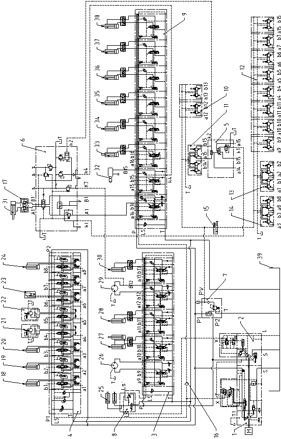
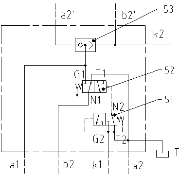
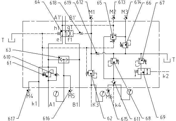
[0037] As shown in the figure, the hydraulic control system of the drilling machine in this embodiment includes a main pump 1, an auxiliary pump 2, a boom cylinder 18, a bucket cylinder 19, a stick cylinder 20, a left travel motor 21, a right travel motor 22, a breaker 23. Boom swing cylinder 24, propulsion cylinder 31, impactor 32, drill boom swing cylinder 33, drill boom pitch cylinder 34, drill boom telescopic cylinder 35, bracket flip cylinder 36, bracket swing cylinder 37, bracket Frame pitch oil cylinder 38 and oil tank 39 are characterized in that: it also includes a first multi-way reversing valve 3, a second multi-way reversing valve 4, a pilot oil control valve group 5, an anti-jamming valve group 6, a pilot oil source valve Group 7, track tensioning valve group 8, third multi-way reversing valve 9, first hydraulic pilot control valve group 10...


PUM


Abstract

The invention discloses a hydraulic control system of a drill loader. The hydraulic control system comprises a primary pump, a secondary pump, a first multi-way directional valve, a second multi-way directional valve, a pilot oil control valve unit, an anti-jamming valve unit, a pilot oil source valve unit, a track tensioning valve unit, a third multi-way directional valve, a first hydraulic pilot control valve unit, a second hydraulic pilot control valve unit, a first hydraulic pilot control valve device, a second hydraulic pilot control valve device, a third hydraulic pilot control valve device, a hand-operated directional valve, a first balance valve and a boom cylinder. The hydraulic control system of the drill loader disclosed by the invention has the advantages that as a multi-stage propulsion manner and impact pressures are set, the drill loader can adapt to different geological conditions, and initiative jamming prevention is effectively realized; when the jamming is caused, the hydraulic control system disclosed by the invention can control an impactor and a propulsion cylinder to switch into light impact and light propulsion operations, blast holes are repaired, and the jamming preventing effect can be effectively improved; and the hydraulic control system of the drill loader disclosed by the invention adopts a load-sensitive technique, so that the efficiency and accuracy of the hydraulic control system of the drill loader are improved.

Description

technical field [0001] The patent of the present invention relates to the technical field of mining comprehensive tunneling equipment, in particular to a hydraulic control system of a mining drilling machine. [0002] Background technique [0003] Drilling machine is a comprehensive tunneling equipment integrating drilling, loading and conveying. It is mainly used in the tunneling of small and medium-sized hard rock roadways in coal mines in my country, and can also be used in tunneling projects in metallurgy, railways, highways, hydropower and other departments. The prospects are extremely bright. The drilling rig mainly includes a pick-up unit, a drilling rig unit, a feed hopper, a walking unit, a frame unit, a support unit, and a transportation unit. [0004] In the existing drilling machine, the control accuracy and control efficiency of the hydraulic control system are not high, the operation control is not convenient enough, and the anti-jamming function is poor, so t...

Claims


Application Information

Patent Timeline
IPC IPC(8): E21D9/10E21B44/00F15B11/02F15B11/16F15B13/06F15B13/12
Inventor 谭正生刁文庆王清峰肖高雄杨林孙章虎朱利民任晓华杨洋郭向勇郝少楠余明姚
Owner CHINA COAL TECH ENG GRP CHONGQING RES INST
Learn More