Gyro-type dynamic self-balancing pan-tilt

A self-balancing, gyro-type technology, applied in the direction of motor vehicles, machines/supports, cameras, etc., can solve the problems of not being able to adapt to various attitudes of the carrier in time, not being able to perform stepless adjustment, and low adjustment accuracy, so as to improve shooting The effects of stability, short action response time, and low energy consumption

Active Publication Date: 2013-03-27
SZ DJI OSMO TECH CO LTD
View PDF9 Cites 46 Cited by
  • Summary
  • Abstract
  • Description
  • Claims
  • Application Information

AI Technical Summary

Problems solved by technology

[0004] The technical problem to be solved by the present invention is that the cloud platform in the prior art has a long response time due to the use of gear transmission, and cannot adapt to various attitudes of the carrie

Method used


Image

  • Gyro-type dynamic self-balancing pan-tilt
  • Gyro-type dynamic self-balancing pan-tilt
  • Gyro-type dynamic self-balancing pan-tilt

Examples


Example Embodiment

[0032] Embodiment one

[0033] like figure 1 As shown, an embodiment of the present invention is provided, a gyro-type dynamic self-balancing two-axis gimbal, which specifically includes a frame assembly, a motor assembly, a control assembly and a shooting device 1 . The frame assembly includes a first bracket 2 and a second bracket 4 , and the shooting device 1 is fixed on the first bracket 2 . The shape of the shooting device 1 is not limited to figure 1 The square shown in , can also be round or other shapes. In order to realize the rotation of the shooting device 1 along the X axis (that is: the rotation axis of the first bracket 2), the first bracket 2 is rotated on the second bracket 4 through the pin shaft at the end. This rotation structure can realize the rotation of the shooting device 1. Rotate with your head up or down. In order to keep the position of the shooting device 1 unchanged, to ensure the stability of taking photos or video recordings, when the vehicl...

Example Embodiment

[0046] Embodiment two

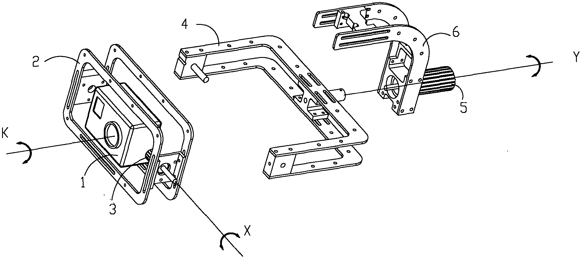
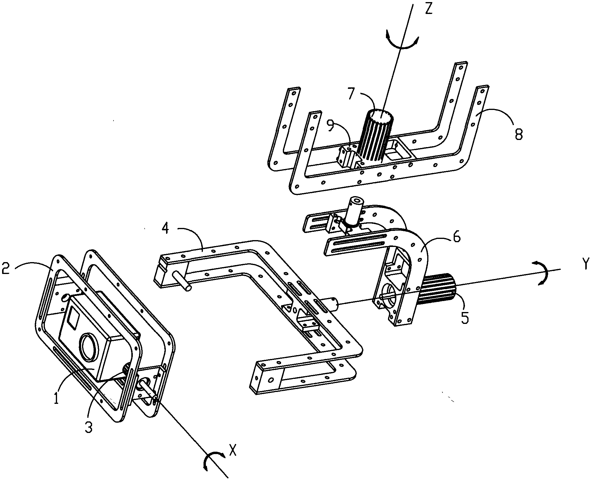
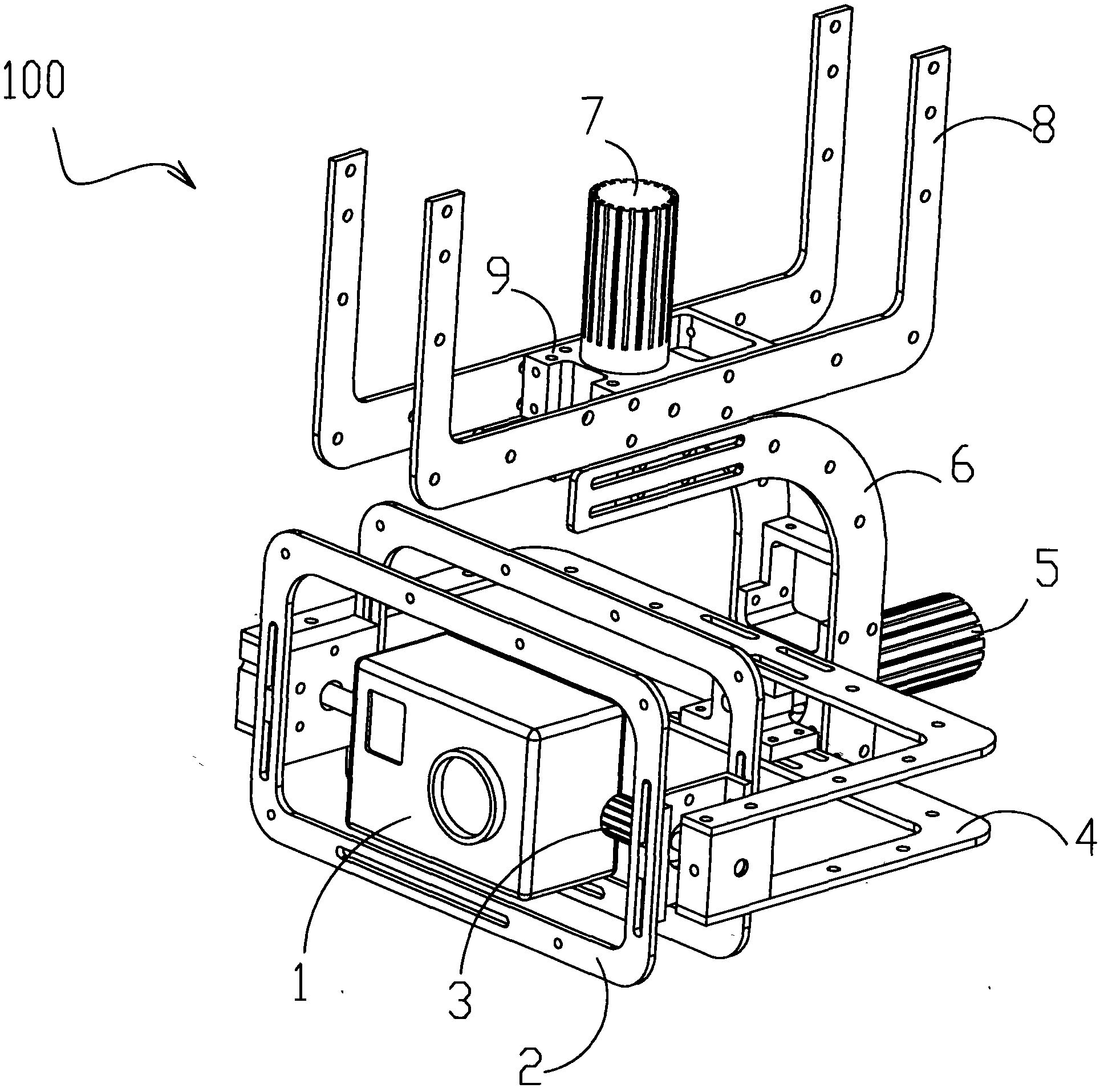
[0047] like figure 2 , image 3 , Figure 4 As shown, it is a preferred embodiment provided by the present invention. The pan / tilt 100 can be rotated by three axes to form a three-axis rotation pan / tilt, which specifically includes a frame assembly, a motor assembly, a control assembly and a shooting device 1 . like figure 2 As shown, the frame assembly includes a first bracket 2 , a second bracket 4 , a third bracket 6 and a connecting bracket 8 . The shooting device 1 is fixed on the first bracket 2. In order to realize the rotation of the shooting device 1 along the X axis (that is: the rotation axis of the first bracket 2), the first bracket 2 and the second bracket 4 are rotated. This rotation structure can realize The head up or down of the shooting device 1 rotates. In order to keep the position of the shooting device 1 unchanged, to ensure the stability of taking photos or video recordings, when the vehicle tilts left or right, the pan-ti...


PUM


Abstract

The invention discloses a gyro-type dynamic self-balancing pan-tilt which comprises a frame component, a motor component, shooting equipment (1) and a control component; the control component comprises a processor and an inertial sensor; the inertial sensor detects the posture information of the shooting equipment (1); the processor controls the motor component according to the posture information; and the motor component directly drives the frame component to rotate in a manner relative to the shooting equipment so as to adjust the shooting angle of the shooting equipment (1). According to the gyro-type dynamic self-balancing pan-tilt, the motor component is adopted as motive power to directly drive the frame component of the pan-tilt, so that less energy is consumed, and the electricity is saved; and meanwhile, the stepless adjustment can be realized in the driving of the motor, the action response time is short, various postures of a carrier body can be adapted to by quickly starting, stopping or timely adjusting the rotating speed, so that the shooting stability of the shooting equipment (1) is improved.

Description

technical field [0001] The present invention relates to an auxiliary device for photography, photography and / or monitoring, in particular to a gyro-type dynamic self-balancing platform, which can be applied to manned aircraft, unmanned aircraft, automobiles, ships, robots, film shooting, handheld devices, etc. field. Background technique [0002] In the field of photography, photography and / or monitoring, during the operation of a carrier equipped with a video camera or camera (for example: aircraft, automobile, ship, robot, human body), due to the high-frequency vibration and low-frequency jitter of the carrier itself, it is necessary to configure The stable self-balancing gimbal is used to carry video cameras and cameras to achieve stable shooting. Most of the stable self-balancing gimbals use electronic equipment to detect the attitude changes of the camera or camera, and control the reverse compensation of the steering gear to achieve the stability of the camera or came...

Claims


Application Information

Patent Timeline
IPC IPC(8): F16M11/12F16M11/18G03B17/56
CPCB64D47/08F16M11/10F16M11/2071F16M11/123F16M13/02B64C2201/127F16M11/18F16M2200/041F16M2200/044B64U2101/30G03B17/561
Inventor 汪滔
Owner SZ DJI OSMO TECH CO LTD
Why Eureka
Try Eureka