Heat pipe radiator of phase change drive loop

A loop heat pipe and radiator technology, applied in indirect heat exchangers, lighting and heating equipment, etc., can solve the problems of vapor-liquid interface deviation, large operating flow resistance, and increased flow resistance, and achieve the elimination of contact thermal resistance , Strengthen the effect of liquid film convection heat transfer

Inactive Publication Date: 2013-03-27
TIANJIN UNIV OF COMMERCE
View PDF4 Cites 12 Cited by
  • Summary
  • Abstract
  • Description
  • Claims
  • Application Information

AI Technical Summary

Problems solved by technology

As we all know, the performance of the capillary core in the heat pipe is the key that directly affects the efficiency of the heat pipe evaporator. If the thermal conductivity of the capillary core is too small, the energy transfer efficiency of the evaporator will be reduced; if it is too large, the vapor-liquid interface will shift to the liquid side, and even Bubbles are generated in the liquid channel of the evaporator; the smaller the effective capillary diameter, the greater the pumping force, but too small a capillary will cause a sharp drop in permeability, resulting in an increase in flow resistance, which in turn will reduce the output head of the evaporator
Therefore, although the scope of LHP application is expanding day by day, the main problem in its flow and heat transfer mechanism is still that the flow of working fluid inside the system is a two-phase flow, which makes the operating flow resistance larger
On the other hand, due to the inevitable phase change at both ends of the evaporation section of the heat pipe, a small part of the mainstream phase change working fluid will flow in the opposite direction, which will also increase the circulation flow resistance.

Method used


Image

  • Heat pipe radiator of phase change drive loop

Examples


Embodiment Construction

[0009] The principle and structure of the present invention will be further described below in conjunction with the accompanying drawings and through specific embodiments. It should be noted that this embodiment is descriptive rather than restrictive, and the protection scope of the present invention is not limited by this embodiment.

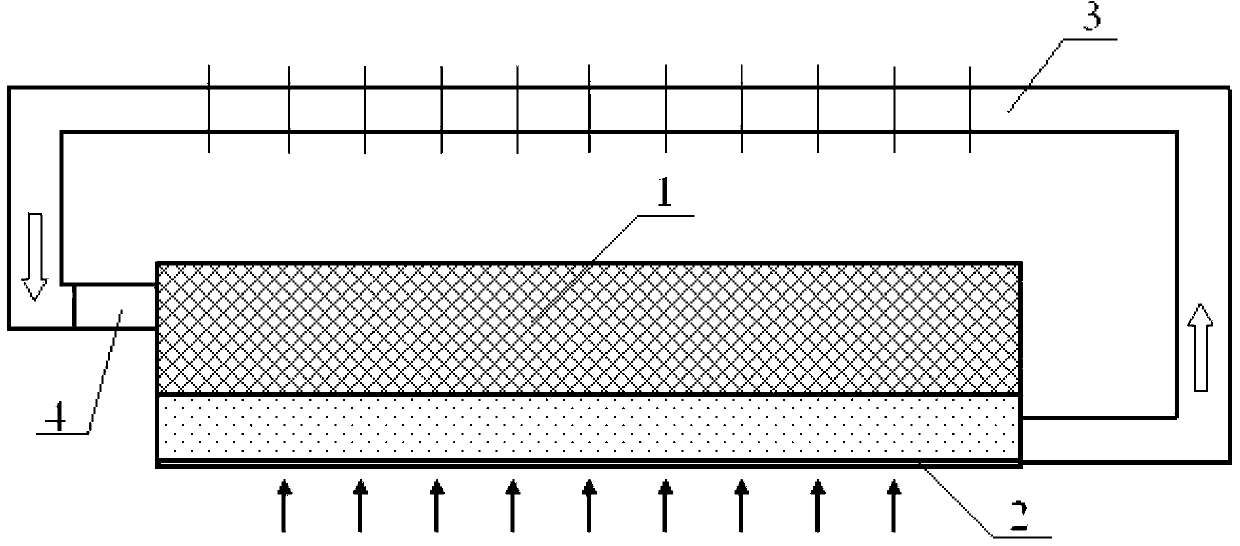
[0010] Phase change drive loop heat pipe radiator, its structure is that the upper part of the evaporation section of the heat pipe is provided with a liquid-absorbing core, the bottom of the evaporation section is a heating surface, the inlet of the working medium circulation pipe is connected to the liquid-absorbing core; the outlet of the working medium circulation pipe is connected to the In the space interlayer formed by the liquid-absorbing core and the heating surface. A liquid storage tank is arranged between the inlet of the working fluid circulation pipe and the liquid-absorbing core. The evaporating section of the heat pipe is a fla...


PUM


Abstract

The invention discloses a heat pipe radiator of a phase change drive loop. According to the heat pipe radiator, a wick is arranged on the upper portion of an evaporation section of a heat pipe, the bottom end of the evaporation section is a heating surface, and an inlet of a working medium circulation pipe is connected with the wick; an outlet of the working medium circulation pipe is connected inside a space interlayer formed by the wick and the heating surface; a liquid storage tank is arranged between the inlet of the working medium circulation pipe and the wick; the evaporation section of the heat pipe is a flat pipe, and the height of the space interlayer formed by the wick and the heating surface is 0.1-2mm; and fins are arranged on the outer side of the working medium circulation pipe to strengthen condensation effects. A heat-transfer mechanism that hydrodynamic forces are driven by phase change to circularly cool a high heating flux heating device is completely a heat-transfer mechanism of a traditional loop heat pipe, and a thermal contact resistance between a uniform temperature board and a radiator bottom board in a traditional radiating method is simultaneously eliminated. Low resistance circulation of the heat pipe can be achieved without any auxiliary gravity, and the heat pipe radiator can be used as an efficient cooling device and used for cooling and radiating various high heating flux heaters.

Description

technical field [0001] The invention belongs to the field of thermal energy engineering, and in particular relates to a loop heat pipe radiator device which drives working medium circulation through phase change. Background technique [0002] For heat dissipation and cooling of high power and high heat flux devices in a limited space, compared with oscillating heat pipe (OHP), pulsating heat pipe (PHP) and loop heat pipe (LHP), LHP has strong heat transfer capacity, high efficiency and good stability. It is characterized by long transmission distance and has been rapidly developed and applied in the fields of aerospace thermal control and electronic cooling. As we all know, the performance of the capillary core in the heat pipe is the key that directly affects the efficiency of the heat pipe evaporator. If the thermal conductivity of the capillary core is too small, the energy transfer efficiency of the evaporator will be reduced; if it is too large, the vapor-liquid interfa...

Claims


Application Information

Patent Timeline
Patent Type & Authority Applications(China)
IPC IPC(8): F28D15/04
CPCF28D15/0266
Inventor 诸凯魏杰
Owner TIANJIN UNIV OF COMMERCE
Why Eureka
Try Eureka